1-4
CHAPTER 1 Using the Robot Safely
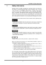
(5) Do not use the robot in environments containing inflammable
gas, etc.
WARNING
• This robot was not designed for operation in environments where inflamma-
ble or explosive substances are present.
• Do not use the robot in environments containing inflammable gas, dust or
liquids. Explosions or fire could otherwise result.
(6) Do not use the robot in locations possibly subject to electro-
magnetic interference, etc.
WARNING
Avoid using the robot in locations subject to electromagnetic interference, elec-
trostatic discharge or radio frequency interference. Malfunction may otherwise
occur.
(7) Use caution when releasing the Z-axis (vertical axis) brake.
WARNING
The Z-axis will slide down when the Z-axis brake is released, causing a hazard-
ous situation.
• Press the emergency stop button and prop up the Z-axis with a support stand
before releasing the brake.
• Use caution not to let your body get caught between the Z-axis and installa-
tion base when releasing the brake to perform direct teach.
(8) Provide safety measures for end effector (gripper, etc.).
WARNING
• End effectors must be designed and manufactured so that they cause no
hazards (for example, loosening of workpiece) even if power (electricity, air
pressure, etc.) is shut off or power fluctuations occur.
• If there is a possible danger that the object gripped by the end effector may
fly off or drop, then provide appropriate safety protection taking into account
the object size, weight, temperature and chemical properties.
Summary of Contents for YK-X Series
Page 1: ...User s Manual ENGLISH E YAMAHA SCARA ROBOT E35 Ver 1 08 YK XG YK X series ...
Page 2: ......
Page 6: ...MEMO ...
Page 10: ...MEMO ...
Page 12: ...MEMO ...
Page 30: ...MEMO ...
Page 36: ...MEMO ...
Page 46: ...3 10 CHAPTER 3 Installation Ground symbol M4 Ground terminal Fig 3 6 Ground terminal ...
Page 78: ...3 42 MEMO ...
Page 80: ...MEMO ...
Page 101: ...4 21 CHAPTER 4 Adjustment Cover Elongated hole Y axis origin sensor stay Bolt Fig 4 8 a ...
Page 102: ...4 22 CHAPTER 4 Adjustment Dog Hex nut Fig 4 8 b Bolt Y axis arm X axis arm Fig 4 8 c ...
Page 119: ...4 39 CHAPTER 4 Adjustment R End effector End effector Z Y X Fig 4 18 ...
Page 120: ...4 40 MEMO ...
Page 122: ...MEMO ...
Page 138: ...5 16 CHAPTER 5 Periodic Inspection M6 16 M5 16 X axis motor Base Fig 5 3 ...
Page 146: ...5 24 CHAPTER 5 Periodic Inspection M3 16 M4 18 X axis arm Fig 5 10 ...
Page 155: ...5 33 CHAPTER 5 Periodic Inspection O ring r M5 14 M6 16 R axis motor Fig 5 17 ...
Page 156: ...5 34 CHAPTER 5 Periodic Inspection M3 14 M3 16 O ring w Fig 5 18 ...
Page 161: ...CHAPTER 6 Increasing the robot operating speed 1 Increasing the robot operating speed 6 1 ...
Page 162: ...MEMO ...
Page 168: ...6 6 MEMO ...
Page 170: ...MEMO ...
Page 177: ...MEMO ...


