

4-4
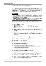
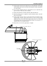
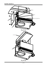
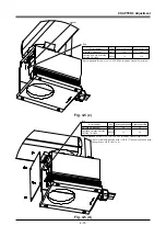
CHAPTER 4 Adjustment
3-2
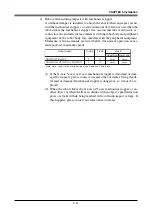
Machine reference
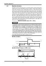
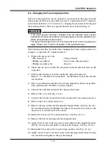
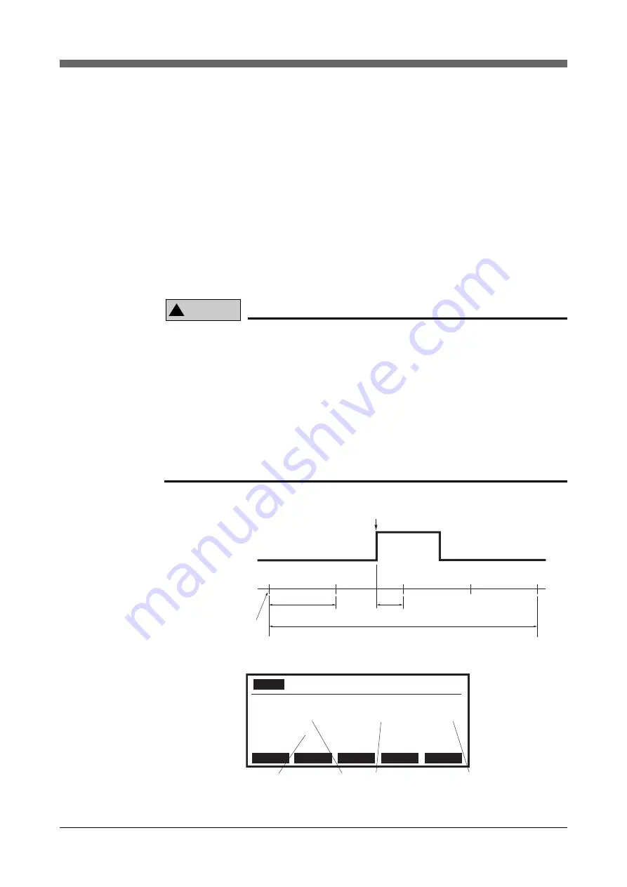
The YK-XG series position detectors are resolvers that have four positions where
absolute reset can be performed per motor revolution. If the sensor method is
used for the absolute reset, the origin position will be set at the positions where
absolute reset can be performed soon after the origin sensor reacts to the dog (the
origin signal is detected). The machine reference means the position relationship
of the position where the robot detects the origin signal to the position where the
absolute reset can be performed soon after detection (see Fig. 4-1). The machine
reference is expressed with the ratio of interval A to interval B shown in Fig. 4-1.
Interval A is the minimum distance between the positions where absolute reset
can be performed and interval B is the distance between the position where the
origin signal is detected and the position where absolute reset can be performed
soon after the origin signal detection. The machine reference value (unit: %) is
displayed on the optional MPB screen.
Machine reference value = B/A
×
100(%)
!
CAUTION
The machine reference must be adjusted within a specified range to keep the
repeatability precision of the absolute reset position (The machine reference is
factory-adjusted prior to shipping). If the origin position is changed, the ma-
chine reference must be readjusted. For information on how to adjust the ma-
chine reference, refer to "3-4 Changing the origin position and adjusting the
machine reference" in Chapter 4. When the temperature of the robot joint sec-
tions is high immediately after the robot has been operated, the machine refer-
ence value might be outside the specified range (40 to 60%). When checking or
adjusting the machine reference value, always make sure that the temperature
of the robot joint sections has returned to room temperature.
Recommended machine reference value: 40 to 60%
Machine reference
Origin signal detection
Origin signal
Resolver
Positions where absolute reset
can be performed
One motor revolution
B
A
ON
OFF
Machine reference display on MPB screen
MANUAL
>RST. ABS
50% [MG] [S0H0J]
Machine reference (%)
M1= 50
M4= 66
M2= 56
M3= 52
M1
M2
M3
M4
M5
R-axis
X-axis
Y-axis
Z-axis
MPB
Fig. 4-1
Summary of Contents for YK-X Series
Page 1: ...User s Manual ENGLISH E YAMAHA SCARA ROBOT E35 Ver 1 08 YK XG YK X series ...
Page 2: ......
Page 6: ...MEMO ...
Page 10: ...MEMO ...
Page 12: ...MEMO ...
Page 30: ...MEMO ...
Page 36: ...MEMO ...
Page 46: ...3 10 CHAPTER 3 Installation Ground symbol M4 Ground terminal Fig 3 6 Ground terminal ...
Page 78: ...3 42 MEMO ...
Page 80: ...MEMO ...
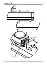
Page 101: ...4 21 CHAPTER 4 Adjustment Cover Elongated hole Y axis origin sensor stay Bolt Fig 4 8 a ...
Page 102: ...4 22 CHAPTER 4 Adjustment Dog Hex nut Fig 4 8 b Bolt Y axis arm X axis arm Fig 4 8 c ...
Page 119: ...4 39 CHAPTER 4 Adjustment R End effector End effector Z Y X Fig 4 18 ...
Page 120: ...4 40 MEMO ...
Page 122: ...MEMO ...
Page 138: ...5 16 CHAPTER 5 Periodic Inspection M6 16 M5 16 X axis motor Base Fig 5 3 ...
Page 146: ...5 24 CHAPTER 5 Periodic Inspection M3 16 M4 18 X axis arm Fig 5 10 ...
Page 155: ...5 33 CHAPTER 5 Periodic Inspection O ring r M5 14 M6 16 R axis motor Fig 5 17 ...
Page 156: ...5 34 CHAPTER 5 Periodic Inspection M3 14 M3 16 O ring w Fig 5 18 ...
Page 161: ...CHAPTER 6 Increasing the robot operating speed 1 Increasing the robot operating speed 6 1 ...
Page 162: ...MEMO ...
Page 168: ...6 6 MEMO ...
Page 170: ...MEMO ...
Page 177: ...MEMO ...


