


6-5
CHAPTER 6 Increasing the robot operating speed
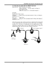
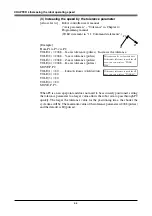
(4) Increasing the speed by the OUT effective position parameter
[Also refer to:]
Robot controller user's manual
("Axis parameters" – "Out effective Position" in Chapter 4)
Programming manual
(OUTPOS statement in "11. Command statements".)
[Example]
From P1 when chuck is open:
OUTPOS (1) = 10000 ... X-axis OUT effective position (pulses) : Increases the OUT effective position.
OUTPOS (2) = 10000 ... Y-axis OUT effective position (pulses)
OUTPOS (3) = 10000 ... Z-axis OUT effective position (pulses)
OUTPOS (4) = 10000 ... R-axis OUT effective position (pulses)
MOVE P, P2, Z=0
DO3 (0) = 1 .................. Chuck closes.
OUTPOS (1) = 2000 ..... Returns the OUT effective position to the default value.
OUTPOS (2) = 2000
OUTPOS (3) = 2000
OUTPOS (4) = 2000
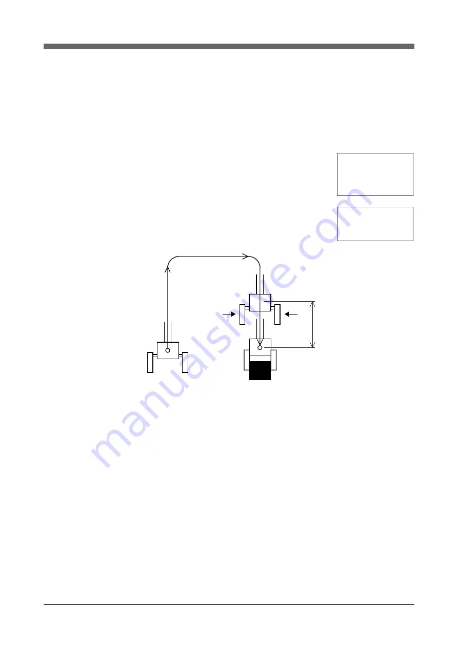
P1
P2
Chuck closed.
Chuck starts closing.
OUT effective position
When all of the X, Y, Z and R axes enter the OUT effective position (10000
pulses prior to P2), the chuck starts closing. By setting the OUT effective posi-
tion larger, the chuck starts closing while the robot arm is still moving at an
earlier point, so that the chuck can grip the workpiece more quickly. The default
value of the OUT effective position is 2000 (pulses).
[Reference]
Relation between X, Y, R-axis rotating angle, Z-axis movement distance and pulse values
The arch position, tolerance and OUT effective position parameters are set in
pulses. For the relation between X, Y, R-axis rotating angle, Z-axis movement
distance and pulse values, refer to the tables listed under item (4) in "4. Setting
the soft limits". (Chapter 4 in this manual)
The OUT effective position can
be set for each axis.
If the same OUT effective
position is used for all axes, you
can write as "OUTPOS 10000".
If the same OUT effective
position is used for all
axes, you can write as
"OUTPOS 2000".
Summary of Contents for YK-X Series
Page 1: ...User s Manual ENGLISH E YAMAHA SCARA ROBOT E35 Ver 1 08 YK XG YK X series ...
Page 2: ......
Page 6: ...MEMO ...
Page 10: ...MEMO ...
Page 12: ...MEMO ...
Page 30: ...MEMO ...
Page 36: ...MEMO ...
Page 46: ...3 10 CHAPTER 3 Installation Ground symbol M4 Ground terminal Fig 3 6 Ground terminal ...
Page 78: ...3 42 MEMO ...
Page 80: ...MEMO ...
Page 101: ...4 21 CHAPTER 4 Adjustment Cover Elongated hole Y axis origin sensor stay Bolt Fig 4 8 a ...
Page 102: ...4 22 CHAPTER 4 Adjustment Dog Hex nut Fig 4 8 b Bolt Y axis arm X axis arm Fig 4 8 c ...
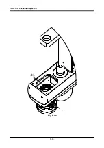
Page 119: ...4 39 CHAPTER 4 Adjustment R End effector End effector Z Y X Fig 4 18 ...
Page 120: ...4 40 MEMO ...
Page 122: ...MEMO ...
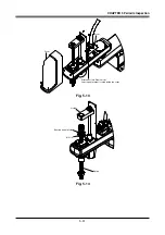
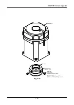
Page 138: ...5 16 CHAPTER 5 Periodic Inspection M6 16 M5 16 X axis motor Base Fig 5 3 ...
Page 146: ...5 24 CHAPTER 5 Periodic Inspection M3 16 M4 18 X axis arm Fig 5 10 ...
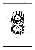
Page 155: ...5 33 CHAPTER 5 Periodic Inspection O ring r M5 14 M6 16 R axis motor Fig 5 17 ...
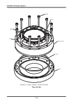
Page 156: ...5 34 CHAPTER 5 Periodic Inspection M3 14 M3 16 O ring w Fig 5 18 ...
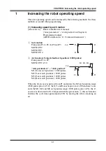
Page 161: ...CHAPTER 6 Increasing the robot operating speed 1 Increasing the robot operating speed 6 1 ...
Page 162: ...MEMO ...
Page 168: ...6 6 MEMO ...
Page 170: ...MEMO ...
Page 177: ...MEMO ...


