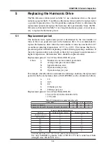
5-15
CHAPTER 5 Periodic Inspection
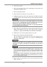
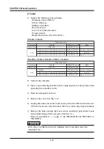
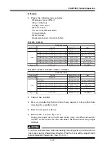
18) Place a new O-ring
w
in the cylindrical section of the base and push the O-
ring to the top end face. (See Fig. 5-4.)
!
CAUTION
Do not allow the O-ring to get caught out of the groove during reassembly. A
problem will occur if the robot is operated with the O-ring left caught out of the
groove.
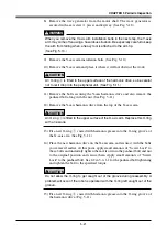
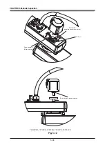
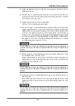
19) Push the X-axis motor into the base while moving the X-axis arm by hand.
Push the X-axis motor into the base while moving the X-axis arm by hand.
Uniformly tighten the four bolts by using the hexagon long bit and torque
wrench, while moving the X-axis arm by hand slowly left and right through
45
°
. If any jamming or catching is felt while moving the axis at this time,
then reassemble from the beginning. (See Fig. 5-3.)
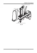
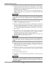
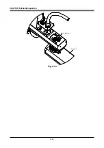
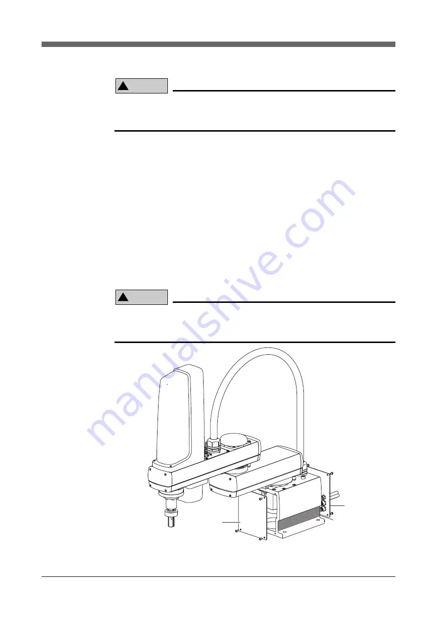
20) Reattach the connectors on the X-axis motor power wire XM and resolver
wire XP. (See Fig. 5-2.) Also reattach the X-axis motor ring-tongue terminal.
21) Reattach the base (robot pedestal) front and rear covers.
22) Go outside the safeguard enclosure.
23) Check that no one is inside the safeguard enclosure, and then turn on the
controller.
!
CAUTION
After the Harmonic drive is replaced, an absolute reset must be performed, and
the standard coordinate and point data must be reset. Refer to "Chapter 4 Ad-
justment" to adjust it.
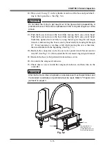
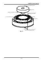
Cover
Cover
The ring terminal for
the X-axis motor is
located behind the cover.
Disconnect the terminal.
Fig. 5-2
Summary of Contents for YK-X Series
Page 1: ...User s Manual ENGLISH E YAMAHA SCARA ROBOT E35 Ver 1 08 YK XG YK X series ...
Page 2: ......
Page 6: ...MEMO ...
Page 10: ...MEMO ...
Page 12: ...MEMO ...
Page 30: ...MEMO ...
Page 36: ...MEMO ...
Page 46: ...3 10 CHAPTER 3 Installation Ground symbol M4 Ground terminal Fig 3 6 Ground terminal ...
Page 78: ...3 42 MEMO ...
Page 80: ...MEMO ...
Page 101: ...4 21 CHAPTER 4 Adjustment Cover Elongated hole Y axis origin sensor stay Bolt Fig 4 8 a ...
Page 102: ...4 22 CHAPTER 4 Adjustment Dog Hex nut Fig 4 8 b Bolt Y axis arm X axis arm Fig 4 8 c ...
Page 119: ...4 39 CHAPTER 4 Adjustment R End effector End effector Z Y X Fig 4 18 ...
Page 120: ...4 40 MEMO ...
Page 122: ...MEMO ...
Page 138: ...5 16 CHAPTER 5 Periodic Inspection M6 16 M5 16 X axis motor Base Fig 5 3 ...
Page 146: ...5 24 CHAPTER 5 Periodic Inspection M3 16 M4 18 X axis arm Fig 5 10 ...
Page 155: ...5 33 CHAPTER 5 Periodic Inspection O ring r M5 14 M6 16 R axis motor Fig 5 17 ...
Page 156: ...5 34 CHAPTER 5 Periodic Inspection M3 14 M3 16 O ring w Fig 5 18 ...
Page 161: ...CHAPTER 6 Increasing the robot operating speed 1 Increasing the robot operating speed 6 1 ...
Page 162: ...MEMO ...
Page 168: ...6 6 MEMO ...
Page 170: ...MEMO ...
Page 177: ...MEMO ...

