


5-29
CHAPTER 5 Periodic Inspection
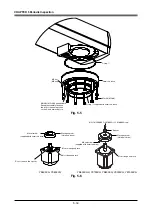
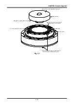
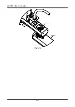
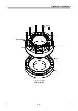
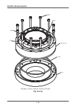
13) Apply the harmonic grease to the new wave generator. See Fig. 5-21 for
applying the grease.
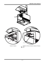
14) Fit the O-ring
t
to the inner side of the new wave generator. Insert the wave
generator into the inner end of the R-axis motor shaft and secure it with the
two setscrews. (See Fig. 5-20.)
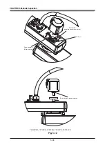
15) Apply harmonic grease to the circular spline.
See Fig. 5-21 for applying grease properly.
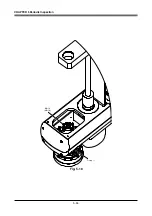
16) Fit a new O-ring
q
coated with harmonic grease into the groove of the shaft.
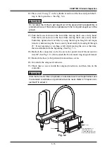
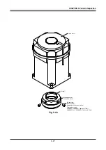
Apply small amounts of "Screw Lock" to the bolts you removed earlier and
tighten them to secure the new harmonic drive. Also return the panhead bolt
and nut to the original position and secure them. Apply small amounts of
"Screw Lock" to the panhead bolt. The panhead bolt tightening torque should
be 90cNm (9kgfcm). On the YK600XGH and YK700XG to YK1000XG,
also apply "Screw Lock" to the dog mounting bolt and tighten it to a torque
of 2.0Nm (20kgfcm). (See Fig. 5-19 (b).)
!
CAUTION
Do not allow the O-ring to get caught out of the groove during reassembly. A
problem will occur if the robot is operated with the O-ring left caught out of
groove.
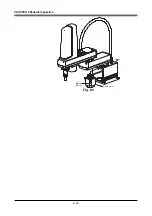
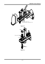
17) Fit the O-ring
w
coated with harmonic grease into the O-ring groove of the
new harmonic drive. (See Fig. 5-18.)
Apply small amounts of "Screw Lock" to the bolts you removed earlier and
tighten them to secure the new harmonic drive to the Y-axis arm from the top
of the Y-axis arm. (See Fig. 5-18.)
!
CAUTION
Do not allow the O-ring to get caught out of the groove during reassembly. A
problem will occur if the robot is operated with the O-ring left caught out of
groove.
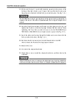
18) Fit the new O-ring
r
coated with harmonic grease into the O-ring groove of
the Y-axis arm.
Insert the R-axis motor into the Y-axis arm while turning the R-axis. Then
tighten the bolts to secure the R-axis motor while turning the R-axis. (See
Fig. 5-17.)
!
CAUTION
Do not allow the O-ring to get caught out of the groove during reassembly. A
problem will occur if the robot is operated with the O-ring left caught out of
groove.
Summary of Contents for YK-X Series
Page 1: ...User s Manual ENGLISH E YAMAHA SCARA ROBOT E35 Ver 1 08 YK XG YK X series ...
Page 2: ......
Page 6: ...MEMO ...
Page 10: ...MEMO ...
Page 12: ...MEMO ...
Page 30: ...MEMO ...
Page 36: ...MEMO ...
Page 46: ...3 10 CHAPTER 3 Installation Ground symbol M4 Ground terminal Fig 3 6 Ground terminal ...
Page 78: ...3 42 MEMO ...
Page 80: ...MEMO ...
Page 101: ...4 21 CHAPTER 4 Adjustment Cover Elongated hole Y axis origin sensor stay Bolt Fig 4 8 a ...
Page 102: ...4 22 CHAPTER 4 Adjustment Dog Hex nut Fig 4 8 b Bolt Y axis arm X axis arm Fig 4 8 c ...
Page 119: ...4 39 CHAPTER 4 Adjustment R End effector End effector Z Y X Fig 4 18 ...
Page 120: ...4 40 MEMO ...
Page 122: ...MEMO ...
Page 138: ...5 16 CHAPTER 5 Periodic Inspection M6 16 M5 16 X axis motor Base Fig 5 3 ...
Page 146: ...5 24 CHAPTER 5 Periodic Inspection M3 16 M4 18 X axis arm Fig 5 10 ...
Page 155: ...5 33 CHAPTER 5 Periodic Inspection O ring r M5 14 M6 16 R axis motor Fig 5 17 ...
Page 156: ...5 34 CHAPTER 5 Periodic Inspection M3 14 M3 16 O ring w Fig 5 18 ...
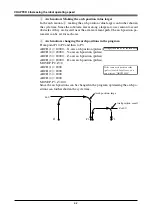
Page 161: ...CHAPTER 6 Increasing the robot operating speed 1 Increasing the robot operating speed 6 1 ...
Page 162: ...MEMO ...
Page 168: ...6 6 MEMO ...
Page 170: ...MEMO ...
Page 177: ...MEMO ...


