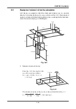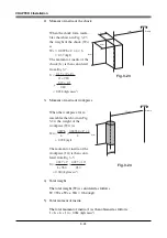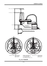
3-20
CHAPTER 3 Installation
6-2
Equation for moment of inertia calculation
Usually the R axis load is not a simple form, and the calculation of the moment of
inertia is not easy. As a method, the load is replaced with several factors that
resemble a simple form for which the moment of inertia can be calculated. The
total of the moment of inertia for these factors is then obtained.
The objects and equations often used for the calculation of the moment of inertia
are shown below. Incidentally, there is the following relation:
J (kgfcmsec
2
) = I (kgm
2
)
×
10.2.
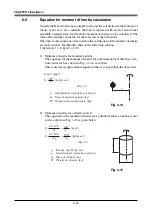
1) Moment of inertia for material particle
The equation for the moment of inertia for a material particle that has a rota-
tion center such as shown in Fig. 3-14 is as follows:
This is used as an approximate equation when x is larger than the object size.
x
J=
Wx
g
2
(kgfcmsec
2
)
g : Gravitational acceleration (cm/sec
2
)
m : Mass of material particle (kg)
... (Eq. 3.1)
I= mx
2
(kgm
2
)
W : Weight of material particle (kgf)
Fig. 3-14
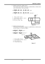
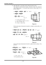
2) Moment of inertia for cylinder (part 1)
The equation for the moment of inertia for a cylinder that has a rotation center
such as shown in Fig. 3-15 is given below.
D
h
J=
ρπ
D h
32g
WD
8g
=
4
2
(kgfcmsec
2
)
... (Eq. 3.2)
I=
ρπ
D h
32
mD
8
=
4
2
(kgm
2
)
ρ
: Density (kg/m
3
, kg/cm
3
)
g : Gravitational acceleration (cm/sec
2
)
m : Mass of cylinder (kg)
W : Weight of cylinder (kgf)
Fig. 3-15
Summary of Contents for YK-X Series
Page 1: ...User s Manual ENGLISH E YAMAHA SCARA ROBOT E35 Ver 1 08 YK XG YK X series ...
Page 2: ......
Page 6: ...MEMO ...
Page 10: ...MEMO ...
Page 12: ...MEMO ...
Page 30: ...MEMO ...
Page 36: ...MEMO ...
Page 46: ...3 10 CHAPTER 3 Installation Ground symbol M4 Ground terminal Fig 3 6 Ground terminal ...
Page 78: ...3 42 MEMO ...
Page 80: ...MEMO ...
Page 101: ...4 21 CHAPTER 4 Adjustment Cover Elongated hole Y axis origin sensor stay Bolt Fig 4 8 a ...
Page 102: ...4 22 CHAPTER 4 Adjustment Dog Hex nut Fig 4 8 b Bolt Y axis arm X axis arm Fig 4 8 c ...
Page 119: ...4 39 CHAPTER 4 Adjustment R End effector End effector Z Y X Fig 4 18 ...
Page 120: ...4 40 MEMO ...
Page 122: ...MEMO ...
Page 138: ...5 16 CHAPTER 5 Periodic Inspection M6 16 M5 16 X axis motor Base Fig 5 3 ...
Page 146: ...5 24 CHAPTER 5 Periodic Inspection M3 16 M4 18 X axis arm Fig 5 10 ...
Page 155: ...5 33 CHAPTER 5 Periodic Inspection O ring r M5 14 M6 16 R axis motor Fig 5 17 ...
Page 156: ...5 34 CHAPTER 5 Periodic Inspection M3 14 M3 16 O ring w Fig 5 18 ...
Page 161: ...CHAPTER 6 Increasing the robot operating speed 1 Increasing the robot operating speed 6 1 ...
Page 162: ...MEMO ...
Page 168: ...6 6 MEMO ...
Page 170: ...MEMO ...
Page 177: ...MEMO ...

