5 - 39
ENG
STARTER CLUTCH AND A.C. MAGNETO ROTOR
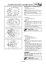
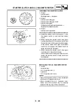
REMOVING THE A.C. MAGNETO ROTOR
1. Remove:
• A.C. magneto rotor cover
NOTE:
Loosen each bolt 1/4 of a turn at a time, in
stages and in a crisscross pattern.
After all of the bolts are fully loosened, remove
them.
2. Remove:
• A.C. magneto rotor nut
1
• spacer
2
NOTE:
• While holding the A.C. magneto rotor
3
with
the sheave holder
4
, loosen the A.C. mag-
neto rotor nut.
• Do not allow the sheave holder to touch the
projection on the A.C. magneto rotor.
3. Remove:
• A.C. magneto rotor
1
(with the flywheel puller set
2
)
• woodruff key
NOTE:
• Remove the A.C. magneto rotor
1
using the
flywheel puller.
• Center the flywheel puller over the A.C. mag-
neto rotor. Make sure after installing the
holding bolts that the clearance between the
flywheel puller and the A.C. magneto rotor is
the same everywhere. If necessary, one
holding bolt maybe turned out slightly to
adjust the flywheel puller’s position.
CAUTION:
Cover the crankshaft end with the box
wrench for protection.
Sheave holder
90890-01701, YS-01880-A
Flywheel puller
90890-01362, YU-33270-B
Summary of Contents for XP500
Page 1: ...2005 XP500 XP500A5VU5 AE1 SERVICE MANUAL...
Page 2: ......
Page 8: ......
Page 9: ...GEN INFO 1...
Page 11: ...GEN INFO...
Page 38: ...SPEC 2...
Page 40: ...SPEC...
Page 68: ...2 28 SPEC OIL FLOW DIAGRAMS 1 Oil strainer 2 Crankshaft...
Page 69: ...2 29 SPEC OIL FLOW DIAGRAMS 1 Clutch 2 Right main journal bearing 3 Main gallery plug...
Page 118: ......
Page 119: ...CHK ADJ 3...
Page 193: ......
Page 194: ...CHAS 4...
Page 198: ...CHAS...
Page 292: ...4 94 CHAS ANTI LOCK BRAKE SYSTEM XP500A...
Page 326: ......
Page 327: ...ENG 5...
Page 331: ...ENG...
Page 424: ...COOL 6...
Page 426: ...COOL...
Page 442: ......
Page 443: ...FI 7...
Page 445: ...FI...
Page 476: ...ELEC 8...
Page 544: ......
Page 545: ...TRBL SHTG 9...
Page 553: ......
Page 556: ......
Page 557: ...YAMAHA MOTOR CO LTD 2500 SHINGAI IWATA SHIZUOKA JAPAN...

