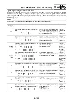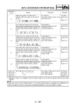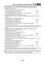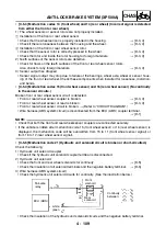
4 - 120
CHAS
ANTI-LOCK BRAKE SYSTEM (XP500A)
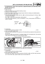
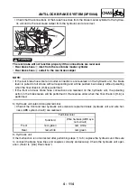
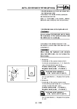
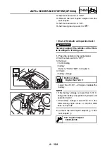
3. Check:
• ABS motor for continuity
Connect the pocket tester (
Ω
×
1) to the ter-
minals of the ABS motor coupler.
Positive tester probe
→
Terminal
1
Negative tester probe
→
Terminal
2
No continuity
→
Replace the hydraulic unit.
There is continuity.
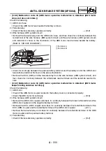
• [D-6] Final check
CHECKING PROCEDURES
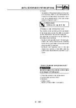
1. Check the brake fluid level in the brake mas-
ter cylinder reservoirs.
2. Check the wheel sensors for proper installa-
tion.
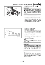
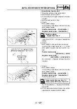
3. Perform hydraulic unit operation test 1 or 2.
4. Delete the malfunction codes.
5. Perform a trial run.
• [D-6-1] Checking the brake fluid level of
the brake master cylinder reservoirs
1. Check:
• brake fluid level
Refer to “CHECKING THE BRAKE FLUID
LEVEL” in chapter 3.
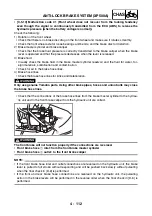
• [D-6-2] Checking the wheel sensors for
proper installation
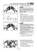
1. Check if the front wheel sensor housing and
the rear wheel sensor housing are installed
correctly. (Refer to “[D-3] Maintenance of
the front wheel sensor and sensor rotor”
and “[D-4] Maintenance of the rear wheel
sensor and sensor rotor”.)
Summary of Contents for XP500
Page 1: ...2005 XP500 XP500A5VU5 AE1 SERVICE MANUAL...
Page 2: ......
Page 8: ......
Page 9: ...GEN INFO 1...
Page 11: ...GEN INFO...
Page 38: ...SPEC 2...
Page 40: ...SPEC...
Page 68: ...2 28 SPEC OIL FLOW DIAGRAMS 1 Oil strainer 2 Crankshaft...
Page 69: ...2 29 SPEC OIL FLOW DIAGRAMS 1 Clutch 2 Right main journal bearing 3 Main gallery plug...
Page 118: ......
Page 119: ...CHK ADJ 3...
Page 193: ......
Page 194: ...CHAS 4...
Page 198: ...CHAS...
Page 292: ...4 94 CHAS ANTI LOCK BRAKE SYSTEM XP500A...
Page 326: ......
Page 327: ...ENG 5...
Page 331: ...ENG...
Page 424: ...COOL 6...
Page 426: ...COOL...
Page 442: ......
Page 443: ...FI 7...
Page 445: ...FI...
Page 476: ...ELEC 8...
Page 544: ......
Page 545: ...TRBL SHTG 9...
Page 553: ......
Page 556: ......
Page 557: ...YAMAHA MOTOR CO LTD 2500 SHINGAI IWATA SHIZUOKA JAPAN...

