2 - 75
SPEC
CABLE ROUTING
Ñ
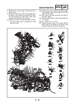
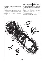
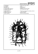
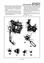
Route the hydraulic unit solenoid lead and ABS
motor lead under the hydraulic unit when install-
ing the unit, making sure not to pinch the leads
between the hydraulic unit and hydraulic unit
bracket.
Ò
Install the ECU (ABS) lead coupler boot all the
way onto the ECU (ABS), making sure that the
section of the boot that covers the ECU (ABS) is
not pinched between the ends of the upper and
lower ECU (ABS) brackets.
Ó
Fasten the grommets on the brake hose (front
brake master cylinder to hydraulic unit) and the
brake hose (rear brake master cylinder to
hydraulic unit) with the brake hose holder.
Ô
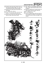
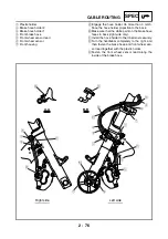
When tightening the union bolt, make sure that
the brake hose contacts the left side of the stop-
per on the hydraulic unit.
Õ
Install the hydraulic unit overflow hose onto the
hydraulic unit, making sure that the hose con-
tacts the unit.
Ö
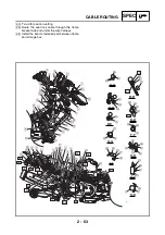
5 ~ 7 mm (0.20 ~ 0.28 in)
E
-
E
D
-
D
C
F
-
F
C
G
-
G
G
G
F
F
D
D
A
B
A
E
E
B
1
2
5
7
8
9
0
A
9
7
8
3
4
9
È
É
Ê
Ë
Ì
Í
Ì
Î
Ê
Ð
Ï
Ñ
Ô
Ó
Ò
Ö
Õ
6
6
3
4
5
Summary of Contents for XP500
Page 1: ...2005 XP500 XP500A5VU5 AE1 SERVICE MANUAL...
Page 2: ......
Page 8: ......
Page 9: ...GEN INFO 1...
Page 11: ...GEN INFO...
Page 38: ...SPEC 2...
Page 40: ...SPEC...
Page 68: ...2 28 SPEC OIL FLOW DIAGRAMS 1 Oil strainer 2 Crankshaft...
Page 69: ...2 29 SPEC OIL FLOW DIAGRAMS 1 Clutch 2 Right main journal bearing 3 Main gallery plug...
Page 118: ......
Page 119: ...CHK ADJ 3...
Page 193: ......
Page 194: ...CHAS 4...
Page 198: ...CHAS...
Page 292: ...4 94 CHAS ANTI LOCK BRAKE SYSTEM XP500A...
Page 326: ......
Page 327: ...ENG 5...
Page 331: ...ENG...
Page 424: ...COOL 6...
Page 426: ...COOL...
Page 442: ......
Page 443: ...FI 7...
Page 445: ...FI...
Page 476: ...ELEC 8...
Page 544: ......
Page 545: ...TRBL SHTG 9...
Page 553: ......
Page 556: ......
Page 557: ...YAMAHA MOTOR CO LTD 2500 SHINGAI IWATA SHIZUOKA JAPAN...

