7 - 3
FI
FUEL INJECTION SYSTEM
EAS00899
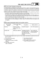
ECU (engine) SELF-DIAGNOSTIC FUNCTION
The ECU (engine) is equipped with a self-diagnostic function in order to ensure that the fuel injec-
tion system is operating normally. If this function detects a malfunction in the system, it immediately
operates the engine under substitute characteristics and illuminates the engine trouble warning light
to alert the rider that a malfunction has occurred in the system. Once a malfunction has been
detected, a fault code is stored in the memory of the ECU (engine).
• To inform the rider that the fuel injection system is not functioning, the engine trouble warning
light flashes when the start switch is being pushed to start the engine.
• If a malfunction is detected in the system by the self-diagnostic function, the ECU (engine) pro-
vides an appropriate substitute characteristic operation, and alerts the rider of the detected mal-
function by illuminating the engine trouble warning light.
• After the engine has been stopped, the lowest fault code number appears on the clock LCD.
Once a fault code has been displayed, it remains stored in the memory of the ECU (engine) until
it is deleted.
EAS00900
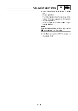
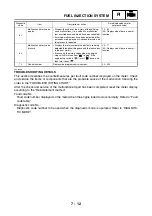
Engine trouble warning light indication and FI system operation
* The warning light flashes when any one of the conditions listed below is present and the start
switch is pushed:
12: Crankshaft position sensor
19: Sidestand switch
(open circuit in the wire to the ECU
(engine))
30: Lean angle cut-off switch
(latch up detected)
41: Lean angle cut-off switch
(open or short-circuit)
50: ECU (engine) internal malfunction
(faulty ECU (engine) memory)
Warning light
indication
ECU (engine) opera-
tion
FI operation
Vehicle operation
Flashing*
Warning provided
when unable to start
engine
Operation stopped
Can not be operated
Remains ON
Malfunction detected
Operated with substi-
tute characteristics in
accordance with the
description of the mal-
function.
Can or cannot be
operated depending
on the fault code
Summary of Contents for XP500
Page 1: ...2005 XP500 XP500A5VU5 AE1 SERVICE MANUAL...
Page 2: ......
Page 8: ......
Page 9: ...GEN INFO 1...
Page 11: ...GEN INFO...
Page 38: ...SPEC 2...
Page 40: ...SPEC...
Page 68: ...2 28 SPEC OIL FLOW DIAGRAMS 1 Oil strainer 2 Crankshaft...
Page 69: ...2 29 SPEC OIL FLOW DIAGRAMS 1 Clutch 2 Right main journal bearing 3 Main gallery plug...
Page 118: ......
Page 119: ...CHK ADJ 3...
Page 193: ......
Page 194: ...CHAS 4...
Page 198: ...CHAS...
Page 292: ...4 94 CHAS ANTI LOCK BRAKE SYSTEM XP500A...
Page 326: ......
Page 327: ...ENG 5...
Page 331: ...ENG...
Page 424: ...COOL 6...
Page 426: ...COOL...
Page 442: ......
Page 443: ...FI 7...
Page 445: ...FI...
Page 476: ...ELEC 8...
Page 544: ......
Page 545: ...TRBL SHTG 9...
Page 553: ......
Page 556: ......
Page 557: ...YAMAHA MOTOR CO LTD 2500 SHINGAI IWATA SHIZUOKA JAPAN...

