2 - 61
SPEC
CABLE ROUTING
À
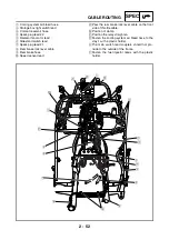
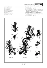
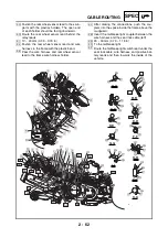
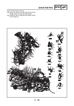
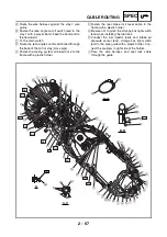
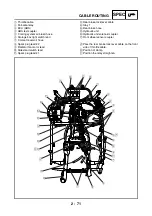
Fasten the O
2
sensor lead to the frame with a
plastic band.
Á
Fasten the starter motor lead and negative bat-
tery lead to the frame with a plastic band. Posi-
tion the band clasp on the bottom of the frame
and face the band end to the outside.
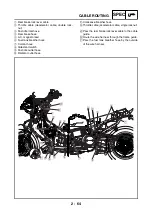
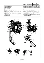
Make sure that the V-belt replacement indica-
tor reset coupler does not project out of the
clamshell cover.
Fasten the O
2
sensor lead and V-belt replace-
ment indicator reset coupler lead to the frame
with a plastic holder.
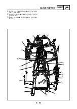
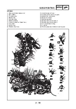
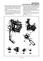
Pass the wire harness and seat lock cable in
the frame holder.
Pass the rear brake lock lever cable under the
coolant pipe.
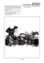
40 ~ 50 mm (1.57 ~ 1.97 in)
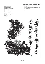
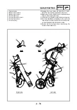
Fasten the wire harness to the frame with the
plastic band. The buckle of the plastic band
should be facing towards the storage box.
A A
A B
A C
A D
A E
A F
Ð
Ñ
Ò
A-A
B-B
D-D
F-F
J-J
K-K
H-H
C-C
E-E
G-G
I-I
P
P
C
B
O
Q
D
R
T
D
D
T
P
U
U
U
P
U
V
S
W
N
X
P
Q
Q
N
A
A
B
B
B
9
8
7
Ó
Ô
Õ
Ö
Ï
6
5
2
1
Î
Í
Ì
Ë
Ê
É
È
AR
AD
AC
AG
AA
AL
AJ
AN
AE
AS
S
M
N
Y
U
U
Q
P
P
P
Q
U
K
J
J
I
H
H
C
D
D
G
G
E
E
F
F
C
I
K
Ø
Ù
Ú Û
Ü
D
E
G
F
H
I
À
ß
Ý
Þ
Ý
AI
N
L
K
J
C
×
4
3
0
A
M
AF
AO
AP
AM
AB
Á
AH
AK
AQ
Summary of Contents for XP500
Page 1: ...2005 XP500 XP500A5VU5 AE1 SERVICE MANUAL...
Page 2: ......
Page 8: ......
Page 9: ...GEN INFO 1...
Page 11: ...GEN INFO...
Page 38: ...SPEC 2...
Page 40: ...SPEC...
Page 68: ...2 28 SPEC OIL FLOW DIAGRAMS 1 Oil strainer 2 Crankshaft...
Page 69: ...2 29 SPEC OIL FLOW DIAGRAMS 1 Clutch 2 Right main journal bearing 3 Main gallery plug...
Page 118: ......
Page 119: ...CHK ADJ 3...
Page 193: ......
Page 194: ...CHAS 4...
Page 198: ...CHAS...
Page 292: ...4 94 CHAS ANTI LOCK BRAKE SYSTEM XP500A...
Page 326: ......
Page 327: ...ENG 5...
Page 331: ...ENG...
Page 424: ...COOL 6...
Page 426: ...COOL...
Page 442: ......
Page 443: ...FI 7...
Page 445: ...FI...
Page 476: ...ELEC 8...
Page 544: ......
Page 545: ...TRBL SHTG 9...
Page 553: ......
Page 556: ......
Page 557: ...YAMAHA MOTOR CO LTD 2500 SHINGAI IWATA SHIZUOKA JAPAN...

