7 - 8
FI
FUEL INJECTION SYSTEM
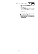
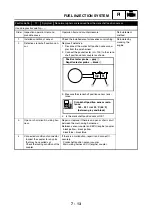
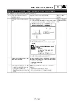
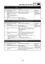
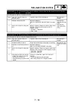
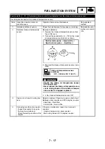
8. Verify the operation of the sensor or actua-
tor.
• Sensor operation
The data representing the operating condi-
tions of the sensor appears on the trip LCD.
• Actuator operation
Set the engine stop switch to “
” to oper-
ate the actuator.
NOTE:
If the engine stop switch is set to “
”, set it to
“
”, and then set it to “
” again.
9. Turn the main switch to “OFF” to cancel the
diagnostic mode.
Summary of Contents for XP500
Page 1: ...2005 XP500 XP500A5VU5 AE1 SERVICE MANUAL...
Page 2: ......
Page 8: ......
Page 9: ...GEN INFO 1...
Page 11: ...GEN INFO...
Page 38: ...SPEC 2...
Page 40: ...SPEC...
Page 68: ...2 28 SPEC OIL FLOW DIAGRAMS 1 Oil strainer 2 Crankshaft...
Page 69: ...2 29 SPEC OIL FLOW DIAGRAMS 1 Clutch 2 Right main journal bearing 3 Main gallery plug...
Page 118: ......
Page 119: ...CHK ADJ 3...
Page 193: ......
Page 194: ...CHAS 4...
Page 198: ...CHAS...
Page 292: ...4 94 CHAS ANTI LOCK BRAKE SYSTEM XP500A...
Page 326: ......
Page 327: ...ENG 5...
Page 331: ...ENG...
Page 424: ...COOL 6...
Page 426: ...COOL...
Page 442: ......
Page 443: ...FI 7...
Page 445: ...FI...
Page 476: ...ELEC 8...
Page 544: ......
Page 545: ...TRBL SHTG 9...
Page 553: ......
Page 556: ......
Page 557: ...YAMAHA MOTOR CO LTD 2500 SHINGAI IWATA SHIZUOKA JAPAN...

