8 - 42
–
+
ELEC
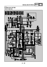
SIGNALING SYSTEM
EAS00796
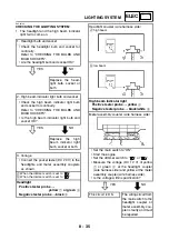
CHECKING THE SIGNALING SYSTEM
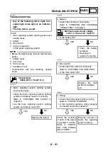
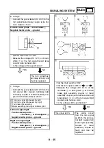
1. The horn fails to sound.
YES
NO
YES
NO
NO
YES
1. Horn switch
• Check the horn switch for continuity.
Refer to “CHECKING THE SWITCHES”.
• Is the horn switch OK?
Replace the left han-
dlebar switch.
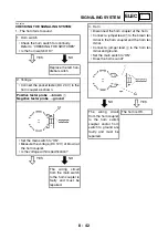
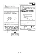
2. Voltage
• Connect the pocket tester (DC 20 V) to the
horn coupler as shown.
Positive tester probe
→
brown
1
Negative tester probe
→
ground
• Set the main switch to “ON”.
• Measure the voltage (DC 12 V) of brown at
the horn coupler.
• Is the voltage within specification?
The wiring circuit
from the main switch
to the horn coupler is
faulty and must be
repaired.
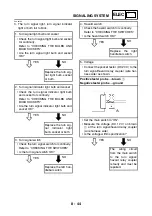
3. Horn
• Disconnect the horn coupler at the horn.
• Connect a jumper lead
1
to the brown ter-
minal in the horn coupler and the horn ter-
minal.
• Connect a jumper lead
2
to the horn ter-
minal and ground.
• Set the main switch to “ON”.
• Does the horn sound?
The wiring circuit
from the horn coupler
to the horn switch
coupler and/or horn
switch to ground are
faulty and must be
repaired.
The horn is OK.
Summary of Contents for XP500
Page 1: ...2005 XP500 XP500A5VU5 AE1 SERVICE MANUAL...
Page 2: ......
Page 8: ......
Page 9: ...GEN INFO 1...
Page 11: ...GEN INFO...
Page 38: ...SPEC 2...
Page 40: ...SPEC...
Page 68: ...2 28 SPEC OIL FLOW DIAGRAMS 1 Oil strainer 2 Crankshaft...
Page 69: ...2 29 SPEC OIL FLOW DIAGRAMS 1 Clutch 2 Right main journal bearing 3 Main gallery plug...
Page 118: ......
Page 119: ...CHK ADJ 3...
Page 193: ......
Page 194: ...CHAS 4...
Page 198: ...CHAS...
Page 292: ...4 94 CHAS ANTI LOCK BRAKE SYSTEM XP500A...
Page 326: ......
Page 327: ...ENG 5...
Page 331: ...ENG...
Page 424: ...COOL 6...
Page 426: ...COOL...
Page 442: ......
Page 443: ...FI 7...
Page 445: ...FI...
Page 476: ...ELEC 8...
Page 544: ......
Page 545: ...TRBL SHTG 9...
Page 553: ......
Page 556: ......
Page 557: ...YAMAHA MOTOR CO LTD 2500 SHINGAI IWATA SHIZUOKA JAPAN...

