BASIC SERVICE INFORMATION
1-51
Checking the connections
Check the leads, couplers, and connectors for
stains, rust, moisture, etc.
1. Disconnect:
• Lead
• Coupler
• Connector
NOTICE
ECA16780
• When disconnecting a coupler, release the
coupler lock, hold both sections of the cou-
pler securely, and then disconnect the cou-
pler.
• There are many types of coupler locks;
therefore, be sure to check the type of cou-
pler lock before disconnecting the coupler.
NOTICE
ECA16790
When disconnecting a connector, do not pull
the leads. Hold both sections of the connec-
tor securely, and then disconnect the con-
nector.
2. Check:
• Lead
• Coupler
• Connector
Moisture
→
Dry with an air blower.
Rust/stains
→
Connect and disconnect sev-
eral times.
3. Connect:
• Lead
• Coupler
• Connector
TIP
• When connecting a coupler or connector, push
both sections of the coupler or connector to-
gether until they are connected securely.
• Make sure all connections are tight.
Summary of Contents for FJR1300A(D)
Page 1: ...2013 SERVICE MANUAL FJR1300A D 1MC 28197 E0 ...
Page 6: ......
Page 8: ......
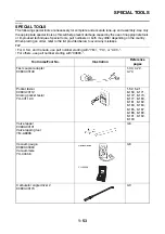
Page 70: ...SPECIAL TOOLS 1 61 ...
Page 101: ...LUBRICATION POINTS AND LUBRICANT TYPES 2 30 ...
Page 104: ...LUBRICATION SYSTEM CHART AND DIAGRAMS 2 33 EAS20410 LUBRICATION DIAGRAMS 5 6 7 1 2 3 4 ...
Page 106: ...LUBRICATION SYSTEM CHART AND DIAGRAMS 2 35 1 3 2 ...
Page 107: ...LUBRICATION SYSTEM CHART AND DIAGRAMS 2 36 1 Main axle 2 Drive axle 3 Oil delivery pipe 1 ...
Page 108: ...LUBRICATION SYSTEM CHART AND DIAGRAMS 2 37 6 5 4 3 2 1 ...
Page 110: ...LUBRICATION SYSTEM CHART AND DIAGRAMS 2 39 1 2 3 4 5 6 7 8 9 ...
Page 112: ...LUBRICATION SYSTEM CHART AND DIAGRAMS 2 41 4 5 3 2 1 9 8 6 7 ...
Page 116: ...COOLING SYSTEM DIAGRAMS 2 45 7 1 2 3 4 5 5 8 9 6 8 9 10 11 12 ...
Page 124: ...CABLE ROUTING 2 53 Horn and radiator left side view A B 1 1 2 3 4 5 5 6 C 7 7 8 ...
Page 132: ...CABLE ROUTING 2 61 Rear fender top view 1 2 3 B C A B ...
Page 138: ...CABLE ROUTING 2 67 ...
Page 141: ......
Page 377: ...MIDDLE GEAR 5 76 Middle driven pinion gear shim Thickness mm 0 10 0 15 0 20 0 30 0 40 0 50 ...
Page 428: ...WATER PUMP 6 15 ...
Page 455: ...IGNITION SYSTEM 8 6 ...
Page 461: ...ELECTRIC STARTING SYSTEM 8 12 ...
Page 465: ...CHARGING SYSTEM 8 16 ...
Page 477: ...SIGNALING SYSTEM 8 28 ...
Page 533: ...FUEL INJECTION SYSTEM 8 84 ...
Page 551: ...CRUISE CONTROL SYSTEM 8 102 ...
Page 555: ...FUEL PUMP SYSTEM 8 106 ...
Page 563: ...ACCESSORY BOX SYSTEM 8 114 ...
Page 573: ...IMMOBILIZER SYSTEM 8 124 ...
Page 577: ...ABS ANTI LOCK BRAKE SYSTEM 8 128 ...
Page 616: ...ELECTRICAL COMPONENTS 8 167 7 1 3 2 18 21 20 19 9 11 12 13 14 15 16 17 6 8 4 5 10 ...
Page 658: ......
Page 659: ......
Page 660: ......


