


ABS (ANTI-LOCK BRAKE SYSTEM)
8-141
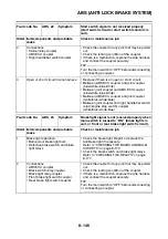
TIP
Vehicle possibly ridden on uneven roads.
Fault code No.
ABS_13
ABS_26
Symptom
Incorrect signal from the front wheel sensor is
detected.
Order Item/components and probable
cause
Check or maintenance job
1
Installed condition of wheel sensor.
Check for looseness. Properly install or replace the
wheel sensor if necessary.
2
Installed condition of wheel bearings,
axle, sensor housing, and sensor ro-
tor.
Check the components for looseness, distortion,
and bends.
Refer to “CHECKING THE FRONT WHEEL” on
page 4-25.
3
Foreign material inside sensor hous-
ing.
Check the interior of the sensor housing and the
surface of the sensor rotor for foreign material,
such as metal particles. Clean the sensor housing
and sensor rotor if necessary.
Refer to “MAINTENANCE OF THE FRONT
WHEEL SENSOR AND SENSOR ROTOR” on
page 4-26.
4
Defective sensor rotor.
Check the surface of the sensor rotor for damage.
If there is visible damage, replace the sensor rotor.
Refer to “MAINTENANCE OF THE FRONT
WHEEL SENSOR AND SENSOR ROTOR” on
page 4-26.
5
Hydraulic unit assembly internal mal-
function.
Replace the hydraulic unit assembly.
Fault code No.
ABS_14
ABS_27
Symptom
Incorrect signal from the rear wheel sensor is
detected.
Order Item/components and probable
cause
Check or maintenance job
1
Installed condition of wheel sensor.
Check for looseness. Properly install or replace the
wheel sensor if necessary.
2
Installed condition of wheel bearings,
axle, sensor housing, and sensor ro-
tor.
Check the components for looseness, distortion,
and bends.
Refer to “CHECKING THE REAR WHEEL” on page
4-34.
3
Foreign material inside sensor hous-
ing.
Check the interior of the sensor housing and the
surface of the sensor rotor for foreign material,
such as metal particles. Clean the sensor housing
and sensor rotor if necessary.
Refer to “MAINTENANCE OF THE REAR WHEEL
SENSOR AND SENSOR ROTOR” on page 4-34.
4
Defective sensor rotor.
Check the surface of the sensor rotor for damage.
If there is visible damage, replace the sensor rotor.
Refer to “MAINTENANCE OF THE REAR WHEEL
SENSOR AND SENSOR ROTOR” on page 4-34.
Summary of Contents for FJR1300A(D)
Page 1: ...2013 SERVICE MANUAL FJR1300A D 1MC 28197 E0 ...
Page 6: ......
Page 8: ......
Page 70: ...SPECIAL TOOLS 1 61 ...
Page 101: ...LUBRICATION POINTS AND LUBRICANT TYPES 2 30 ...
Page 104: ...LUBRICATION SYSTEM CHART AND DIAGRAMS 2 33 EAS20410 LUBRICATION DIAGRAMS 5 6 7 1 2 3 4 ...
Page 106: ...LUBRICATION SYSTEM CHART AND DIAGRAMS 2 35 1 3 2 ...
Page 107: ...LUBRICATION SYSTEM CHART AND DIAGRAMS 2 36 1 Main axle 2 Drive axle 3 Oil delivery pipe 1 ...
Page 108: ...LUBRICATION SYSTEM CHART AND DIAGRAMS 2 37 6 5 4 3 2 1 ...
Page 110: ...LUBRICATION SYSTEM CHART AND DIAGRAMS 2 39 1 2 3 4 5 6 7 8 9 ...
Page 112: ...LUBRICATION SYSTEM CHART AND DIAGRAMS 2 41 4 5 3 2 1 9 8 6 7 ...
Page 116: ...COOLING SYSTEM DIAGRAMS 2 45 7 1 2 3 4 5 5 8 9 6 8 9 10 11 12 ...
Page 124: ...CABLE ROUTING 2 53 Horn and radiator left side view A B 1 1 2 3 4 5 5 6 C 7 7 8 ...
Page 132: ...CABLE ROUTING 2 61 Rear fender top view 1 2 3 B C A B ...
Page 138: ...CABLE ROUTING 2 67 ...
Page 141: ......
Page 377: ...MIDDLE GEAR 5 76 Middle driven pinion gear shim Thickness mm 0 10 0 15 0 20 0 30 0 40 0 50 ...
Page 428: ...WATER PUMP 6 15 ...
Page 455: ...IGNITION SYSTEM 8 6 ...
Page 461: ...ELECTRIC STARTING SYSTEM 8 12 ...
Page 465: ...CHARGING SYSTEM 8 16 ...
Page 477: ...SIGNALING SYSTEM 8 28 ...
Page 533: ...FUEL INJECTION SYSTEM 8 84 ...
Page 551: ...CRUISE CONTROL SYSTEM 8 102 ...
Page 555: ...FUEL PUMP SYSTEM 8 106 ...
Page 563: ...ACCESSORY BOX SYSTEM 8 114 ...
Page 573: ...IMMOBILIZER SYSTEM 8 124 ...
Page 577: ...ABS ANTI LOCK BRAKE SYSTEM 8 128 ...
Page 616: ...ELECTRICAL COMPONENTS 8 167 7 1 3 2 18 21 20 19 9 11 12 13 14 15 16 17 6 8 4 5 10 ...
Page 658: ......
Page 659: ......
Page 660: ......