


REAR BRAKE
4-60
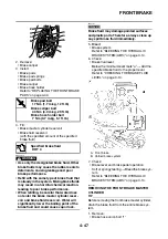
4. Remove:
• Rear brake caliper bolts
• Rear brake caliper
5. Install:
• Brake pad springs
• Rear brake pads
• Brake pad shims
• Rear brake caliper bolts
• Rear brake caliper
Refer to “REPLACING THE REAR BRAKE
PADS” on page 4-56.
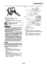
6. Fill:
• Brake fluid reservoir
(with the specified amount of the specified
brake fluid)
WARNING
EWA13090
• Use only the designated brake fluid. Other
brake fluids may cause the rubber seals to
deteriorate, causing leakage and poor
brake performance.
• Refill with the same type of brake fluid that
is already in the system. Mixing brake fluids
may result in a harmful chemical reaction,
leading to poor brake performance.
• When refilling, be careful that water does
not enter the brake fluid reservoir. Water
will significantly lower the boiling point of
the brake fluid and could cause vapor lock.
NOTICE
ECA13540
Brake fluid may damage painted surfaces
and plastic parts. Therefore, always clean up
any spilt brake fluid immediately.
7. Bleed:
• Brake system
Refer to “BLEEDING THE HYDRAULIC
BRAKE SYSTEM (ABS)” on page 3-14.
8. Check:
• Brake fluid level
Below the minimum level mark “a”
→
Add the
specified brake fluid to the proper level.
Refer to “CHECKING THE BRAKE FLUID
LEVEL” on page 3-14.
9. Check:
• Brake pedal operation
Soft or spongy feeling
→
Bleed the brake sys-
tem.
Refer to “BLEEDING THE HYDRAULIC
BRAKE SYSTEM (ABS)” on page 3-14.
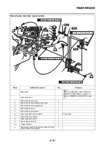
EAS22700
REMOVING THE REAR BRAKE MASTER
CYLINDER
TIP
Before removing the rear brake master cylinder,
drain the brake fluid from the entire brake sys-
tem.
1. Remove:
• Brake hose union bolt “1”
• Copper washers “2”
• Brake hose (rear brake master cylinder to
brake pipe/middle joint assembly) “3”
TIP
To collect any remaining brake fluid, place a
container under the master cylinder and the end
of the brake hose.
EAS22720
CHECKING THE REAR BRAKE MASTER
CYLINDER
1. Check:
• Brake master cylinder
Damage/scratches/wear
→
Replace.
• Brake fluid delivery passages
(brake master cylinder body)
Obstruction
→
Blow out with compressed air.
T
R
.
.
Rear brake caliper bolt
27 Nm (2.7 m·kg, 19 ft·lb)
Specified brake fluid
DOT 4
2
3
1
Summary of Contents for FJR1300A(D)
Page 1: ...2013 SERVICE MANUAL FJR1300A D 1MC 28197 E0 ...
Page 6: ......
Page 8: ......
Page 70: ...SPECIAL TOOLS 1 61 ...
Page 101: ...LUBRICATION POINTS AND LUBRICANT TYPES 2 30 ...
Page 104: ...LUBRICATION SYSTEM CHART AND DIAGRAMS 2 33 EAS20410 LUBRICATION DIAGRAMS 5 6 7 1 2 3 4 ...
Page 106: ...LUBRICATION SYSTEM CHART AND DIAGRAMS 2 35 1 3 2 ...
Page 107: ...LUBRICATION SYSTEM CHART AND DIAGRAMS 2 36 1 Main axle 2 Drive axle 3 Oil delivery pipe 1 ...
Page 108: ...LUBRICATION SYSTEM CHART AND DIAGRAMS 2 37 6 5 4 3 2 1 ...
Page 110: ...LUBRICATION SYSTEM CHART AND DIAGRAMS 2 39 1 2 3 4 5 6 7 8 9 ...
Page 112: ...LUBRICATION SYSTEM CHART AND DIAGRAMS 2 41 4 5 3 2 1 9 8 6 7 ...
Page 116: ...COOLING SYSTEM DIAGRAMS 2 45 7 1 2 3 4 5 5 8 9 6 8 9 10 11 12 ...
Page 124: ...CABLE ROUTING 2 53 Horn and radiator left side view A B 1 1 2 3 4 5 5 6 C 7 7 8 ...
Page 132: ...CABLE ROUTING 2 61 Rear fender top view 1 2 3 B C A B ...
Page 138: ...CABLE ROUTING 2 67 ...
Page 141: ......
Page 377: ...MIDDLE GEAR 5 76 Middle driven pinion gear shim Thickness mm 0 10 0 15 0 20 0 30 0 40 0 50 ...
Page 428: ...WATER PUMP 6 15 ...
Page 455: ...IGNITION SYSTEM 8 6 ...
Page 461: ...ELECTRIC STARTING SYSTEM 8 12 ...
Page 465: ...CHARGING SYSTEM 8 16 ...
Page 477: ...SIGNALING SYSTEM 8 28 ...
Page 533: ...FUEL INJECTION SYSTEM 8 84 ...
Page 551: ...CRUISE CONTROL SYSTEM 8 102 ...
Page 555: ...FUEL PUMP SYSTEM 8 106 ...
Page 563: ...ACCESSORY BOX SYSTEM 8 114 ...
Page 573: ...IMMOBILIZER SYSTEM 8 124 ...
Page 577: ...ABS ANTI LOCK BRAKE SYSTEM 8 128 ...
Page 616: ...ELECTRICAL COMPONENTS 8 167 7 1 3 2 18 21 20 19 9 11 12 13 14 15 16 17 6 8 4 5 10 ...
Page 658: ......
Page 659: ......
Page 660: ......