


FEATURES
1-45
1. Use the code re-registering key to start the
engine.
TIP
Make sure there are no other immobilizer keys
close to the main switch, and do not keep more
than one immobilizer key on the same key ring!
Immobilizer system keys may cause signal inter-
ference, which may prevent the engine from
starting.
2. If the engine starts, turn it off, and try starting
the engine with the standard keys.
3. If one or both of the standard keys do not start
the engine, take the vehicle, the code re-reg-
istering key and both standard keys.
If the information display indicates any fault
codes, note the code number, and then
check the immobilizer system. (Refer to “IM-
MOBILIZER SYSTEM” on page 8-115.)
NOTICE
ECA1MC1010
If the display indicates a fault code, the vehi-
cle should be checked as soon as possible
in order to avoid engine damage.
D-mode (Drive mode)
D-mode is an electronically controlled engine
performance system with two mode selections
(touring mode “T” and sports mode “S”).
Push the drive mode switch “MODE” to switch
between modes.
TIP
Before using D-mode, make sure you under-
stand its operation along with the operation of
the drive mode switch.
Touring mode “T”
The touring mode “T” is suitable for various
riding conditions.
This mode allows the rider to enjoy smooth driv-
ability from the low-speed range to the high-
speed range.
Sports mode “S”
This mode offers a sportier engine response in
the low- to mid-speed range compared to the
touring mode.
Drive mode switch “MODE”
WARNING
EWA1MC1022
Do not change the D-mode while the vehicle
is moving.
Using this switch changes the drive mode to
touring mode “T” or sports mode “S”.
The throttle grip must be completely closed in or-
der to change the drive mode.
The selected mode is shown on the drive mode
display.
The drive mode cannot be changed while the
cruise control system is operating.
1. Drive mode switch “MODE”
STOP
MODE
RU
N
ST
AR
T
1
Summary of Contents for FJR1300A(D)
Page 1: ...2013 SERVICE MANUAL FJR1300A D 1MC 28197 E0 ...
Page 6: ......
Page 8: ......
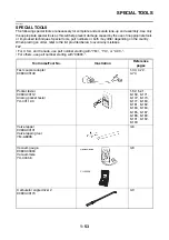
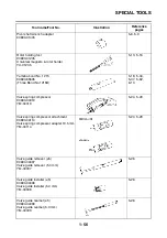
Page 70: ...SPECIAL TOOLS 1 61 ...
Page 101: ...LUBRICATION POINTS AND LUBRICANT TYPES 2 30 ...
Page 104: ...LUBRICATION SYSTEM CHART AND DIAGRAMS 2 33 EAS20410 LUBRICATION DIAGRAMS 5 6 7 1 2 3 4 ...
Page 106: ...LUBRICATION SYSTEM CHART AND DIAGRAMS 2 35 1 3 2 ...
Page 107: ...LUBRICATION SYSTEM CHART AND DIAGRAMS 2 36 1 Main axle 2 Drive axle 3 Oil delivery pipe 1 ...
Page 108: ...LUBRICATION SYSTEM CHART AND DIAGRAMS 2 37 6 5 4 3 2 1 ...
Page 110: ...LUBRICATION SYSTEM CHART AND DIAGRAMS 2 39 1 2 3 4 5 6 7 8 9 ...
Page 112: ...LUBRICATION SYSTEM CHART AND DIAGRAMS 2 41 4 5 3 2 1 9 8 6 7 ...
Page 116: ...COOLING SYSTEM DIAGRAMS 2 45 7 1 2 3 4 5 5 8 9 6 8 9 10 11 12 ...
Page 124: ...CABLE ROUTING 2 53 Horn and radiator left side view A B 1 1 2 3 4 5 5 6 C 7 7 8 ...
Page 132: ...CABLE ROUTING 2 61 Rear fender top view 1 2 3 B C A B ...
Page 138: ...CABLE ROUTING 2 67 ...
Page 141: ......
Page 377: ...MIDDLE GEAR 5 76 Middle driven pinion gear shim Thickness mm 0 10 0 15 0 20 0 30 0 40 0 50 ...
Page 428: ...WATER PUMP 6 15 ...
Page 455: ...IGNITION SYSTEM 8 6 ...
Page 461: ...ELECTRIC STARTING SYSTEM 8 12 ...
Page 465: ...CHARGING SYSTEM 8 16 ...
Page 477: ...SIGNALING SYSTEM 8 28 ...
Page 533: ...FUEL INJECTION SYSTEM 8 84 ...
Page 551: ...CRUISE CONTROL SYSTEM 8 102 ...
Page 555: ...FUEL PUMP SYSTEM 8 106 ...
Page 563: ...ACCESSORY BOX SYSTEM 8 114 ...
Page 573: ...IMMOBILIZER SYSTEM 8 124 ...
Page 577: ...ABS ANTI LOCK BRAKE SYSTEM 8 128 ...
Page 616: ...ELECTRICAL COMPONENTS 8 167 7 1 3 2 18 21 20 19 9 11 12 13 14 15 16 17 6 8 4 5 10 ...
Page 658: ......
Page 659: ......
Page 660: ......