IMPORTANT INFORMATION
1-46
EAS20180
IMPORTANT INFORMATION
EAS20190
PREPARATION FOR REMOVAL AND
DISASSEMBLY
1. Before removal and disassembly, remove all
dirt, mud, dust and foreign material.
2. Use only the proper tools and cleaning equip-
ment.
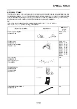
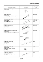
Refer to “SPECIAL TOOLS” on page 1-53.
3. When disassembling, always keep mated
parts together. This includes gears, cylinders,
pistons and other parts that have been “mat-
ed” through normal wear. Mated parts must
always be reused or replaced as an assem-
bly.
4. During disassembly, clean all of the parts and
place them in trays in the order of disassem-
bly. This will speed up assembly and allow for
the correct installation of all parts.
5. Keep all parts away from any source of fire.
EAS20200
REPLACEMENT PARTS
Use only genuine Yamaha parts for all replace-
ments. Use oil and grease recommended by
Yamaha for all lubrication jobs. Other brands
may be similar in function and appearance, but
inferior in quality.
EAS20210
GASKETS, OIL SEALS AND O-RINGS
1. When overhauling the engine, replace all
gaskets, seals and O-rings. All gasket surfac-
es, oil seal lips and O-rings must be cleaned.
2. During reassembly, properly oil all mating
parts and bearings and lubricate the oil seal
lips with grease.
EAS20220
LOCK WASHERS/PLATES AND COTTER
PINS
After removal, replace all lock washers/plates
“1” and cotter pins. After the bolt or nut has been
tightened to specification, bend the lock tabs
along a flat of the bolt or nut.
1. Oil
2. Lip
3. Spring
4. Grease
Summary of Contents for FJR1300A(D)
Page 1: ...2013 SERVICE MANUAL FJR1300A D 1MC 28197 E0 ...
Page 6: ......
Page 8: ......
Page 70: ...SPECIAL TOOLS 1 61 ...
Page 101: ...LUBRICATION POINTS AND LUBRICANT TYPES 2 30 ...
Page 104: ...LUBRICATION SYSTEM CHART AND DIAGRAMS 2 33 EAS20410 LUBRICATION DIAGRAMS 5 6 7 1 2 3 4 ...
Page 106: ...LUBRICATION SYSTEM CHART AND DIAGRAMS 2 35 1 3 2 ...
Page 107: ...LUBRICATION SYSTEM CHART AND DIAGRAMS 2 36 1 Main axle 2 Drive axle 3 Oil delivery pipe 1 ...
Page 108: ...LUBRICATION SYSTEM CHART AND DIAGRAMS 2 37 6 5 4 3 2 1 ...
Page 110: ...LUBRICATION SYSTEM CHART AND DIAGRAMS 2 39 1 2 3 4 5 6 7 8 9 ...
Page 112: ...LUBRICATION SYSTEM CHART AND DIAGRAMS 2 41 4 5 3 2 1 9 8 6 7 ...
Page 116: ...COOLING SYSTEM DIAGRAMS 2 45 7 1 2 3 4 5 5 8 9 6 8 9 10 11 12 ...
Page 124: ...CABLE ROUTING 2 53 Horn and radiator left side view A B 1 1 2 3 4 5 5 6 C 7 7 8 ...
Page 132: ...CABLE ROUTING 2 61 Rear fender top view 1 2 3 B C A B ...
Page 138: ...CABLE ROUTING 2 67 ...
Page 141: ......
Page 377: ...MIDDLE GEAR 5 76 Middle driven pinion gear shim Thickness mm 0 10 0 15 0 20 0 30 0 40 0 50 ...
Page 428: ...WATER PUMP 6 15 ...
Page 455: ...IGNITION SYSTEM 8 6 ...
Page 461: ...ELECTRIC STARTING SYSTEM 8 12 ...
Page 465: ...CHARGING SYSTEM 8 16 ...
Page 477: ...SIGNALING SYSTEM 8 28 ...
Page 533: ...FUEL INJECTION SYSTEM 8 84 ...
Page 551: ...CRUISE CONTROL SYSTEM 8 102 ...
Page 555: ...FUEL PUMP SYSTEM 8 106 ...
Page 563: ...ACCESSORY BOX SYSTEM 8 114 ...
Page 573: ...IMMOBILIZER SYSTEM 8 124 ...
Page 577: ...ABS ANTI LOCK BRAKE SYSTEM 8 128 ...
Page 616: ...ELECTRICAL COMPONENTS 8 167 7 1 3 2 18 21 20 19 9 11 12 13 14 15 16 17 6 8 4 5 10 ...
Page 658: ......
Page 659: ......
Page 660: ......


