


TIGHTENING TORQUES
2-20
TIP
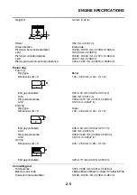
Cylinder head bolt
Tighten the cylinder head bolts to 25 Nm (2.5 m·kg, 18 ft·lb) in the proper tightening sequence, loosen
and retighten the bolts to 25 Nm (2.5 m·kg, 18 ft·lb) in the proper tightening sequence, and then tighten
them further to reach the specified angle 175–185° in the proper tightening sequence.
Cylinder head tightening sequence:
TIP
Connecting rod nut
Tighten the connecting rod nuts to 20 Nm (2.0 m·kg, 14 ft·lb), and then tighten them further to reach the
specified angle 115–125°.
TIP
Crankcase bolt
Tighten the crankcase bolts to 20 Nm (2.0 m·kg, 14 ft·lb) in the proper tightening sequence, loosen and
retighten the bolts to 20 Nm (2.0 m·kg, 14 ft·lb) in the proper tightening sequence, and then tighten them
further to reach the specified angle 115–125° in the proper tightening sequence.
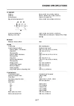
Radiator cover bolt
M6
2
7 Nm (0.7 m·kg, 5.1 ft·lb)
Radiator bracket bolt
M6
1
10 Nm (1.0 m·kg, 7.2 ft·lb)
Coolant reservoir bolt
M6
2
7 Nm (0.7 m·kg, 5.1 ft·lb)
Coolant reservoir bracket bolt
M6
2
7 Nm (0.7 m·kg, 5.1 ft·lb)
Item
Thread
size
Q’ty
Tightening torque
Remarks
LT
Summary of Contents for FJR1300A(D)
Page 1: ...2013 SERVICE MANUAL FJR1300A D 1MC 28197 E0 ...
Page 6: ......
Page 8: ......
Page 70: ...SPECIAL TOOLS 1 61 ...
Page 101: ...LUBRICATION POINTS AND LUBRICANT TYPES 2 30 ...
Page 104: ...LUBRICATION SYSTEM CHART AND DIAGRAMS 2 33 EAS20410 LUBRICATION DIAGRAMS 5 6 7 1 2 3 4 ...
Page 106: ...LUBRICATION SYSTEM CHART AND DIAGRAMS 2 35 1 3 2 ...
Page 107: ...LUBRICATION SYSTEM CHART AND DIAGRAMS 2 36 1 Main axle 2 Drive axle 3 Oil delivery pipe 1 ...
Page 108: ...LUBRICATION SYSTEM CHART AND DIAGRAMS 2 37 6 5 4 3 2 1 ...
Page 110: ...LUBRICATION SYSTEM CHART AND DIAGRAMS 2 39 1 2 3 4 5 6 7 8 9 ...
Page 112: ...LUBRICATION SYSTEM CHART AND DIAGRAMS 2 41 4 5 3 2 1 9 8 6 7 ...
Page 116: ...COOLING SYSTEM DIAGRAMS 2 45 7 1 2 3 4 5 5 8 9 6 8 9 10 11 12 ...
Page 124: ...CABLE ROUTING 2 53 Horn and radiator left side view A B 1 1 2 3 4 5 5 6 C 7 7 8 ...
Page 132: ...CABLE ROUTING 2 61 Rear fender top view 1 2 3 B C A B ...
Page 138: ...CABLE ROUTING 2 67 ...
Page 141: ......
Page 377: ...MIDDLE GEAR 5 76 Middle driven pinion gear shim Thickness mm 0 10 0 15 0 20 0 30 0 40 0 50 ...
Page 428: ...WATER PUMP 6 15 ...
Page 455: ...IGNITION SYSTEM 8 6 ...
Page 461: ...ELECTRIC STARTING SYSTEM 8 12 ...
Page 465: ...CHARGING SYSTEM 8 16 ...
Page 477: ...SIGNALING SYSTEM 8 28 ...
Page 533: ...FUEL INJECTION SYSTEM 8 84 ...
Page 551: ...CRUISE CONTROL SYSTEM 8 102 ...
Page 555: ...FUEL PUMP SYSTEM 8 106 ...
Page 563: ...ACCESSORY BOX SYSTEM 8 114 ...
Page 573: ...IMMOBILIZER SYSTEM 8 124 ...
Page 577: ...ABS ANTI LOCK BRAKE SYSTEM 8 128 ...
Page 616: ...ELECTRICAL COMPONENTS 8 167 7 1 3 2 18 21 20 19 9 11 12 13 14 15 16 17 6 8 4 5 10 ...
Page 658: ......
Page 659: ......
Page 660: ......