


FEATURES
1-42
2. Push the menu switch “MENU” to display
“TIME-2” and “TIME-3”. To reset a time trip,
push the “RESET” button to select the item to
reset.
3. While the selected item is flashing, push the
“RESET” button for at least 2 seconds.
4. Push the menu switch “MENU” to return to
the setting mode menu.
Selecting the units
1. Use the select switch to highlight “Unit”.
2. Push the menu switch “MENU”. The unit set-
ting display will be shown and “km or mile”
(for the UK only) or “km/L or L/100km” (ex-
cept for the UK) will flash in the display.
TIP
• For the UK: Continue with the following steps.
• Except for the UK: Skip steps 3-5.
3. Push the menu switch “MENU”. “km” or “mile”
will flash in the display.
4. Use the select switch to select “km” or “mile”,
and then push the menu switch “MENU”.
TIP
When “km” is selected, “L/100km” or “km/L” can
be set as the fuel consumption units. To set the
fuel consumption units, proceed as follows. If
“mile” was selected, skip steps 5 and 6.
5. Use the select switch to select “km/L or
L/100km”.
6. Push the menu switch “MENU”, use the se-
lect switch to select “L/100km” or “km/L”, and
then push the menu switch “MENU” again.
7. Use the select switch to highlight “ ”, and
then push the menu switch “MENU” to return
to the setting mode menu.
Selecting the display items
1. Use the select switch to highlight “Display”.
TIME-2
0:07
TIME-3
0:07
Time Trip
MENU
Grip Warmer
Maintenance
Time Trip
Unit
Display
Brightness
Clock
Unit
Km or mile
km
km/L or L/100km
km/L
Unit
Km or mile
km
km/L or L/100km
km/L
Unit
Km or mile
km
km/L or L/100km
km/L
MENU
Grip Warmer
Maintenance
Time Trip
Unit
Display
Brightness
Clock
Summary of Contents for FJR1300A(D)
Page 1: ...2013 SERVICE MANUAL FJR1300A D 1MC 28197 E0 ...
Page 6: ......
Page 8: ......
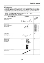
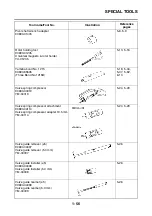
Page 70: ...SPECIAL TOOLS 1 61 ...
Page 101: ...LUBRICATION POINTS AND LUBRICANT TYPES 2 30 ...
Page 104: ...LUBRICATION SYSTEM CHART AND DIAGRAMS 2 33 EAS20410 LUBRICATION DIAGRAMS 5 6 7 1 2 3 4 ...
Page 106: ...LUBRICATION SYSTEM CHART AND DIAGRAMS 2 35 1 3 2 ...
Page 107: ...LUBRICATION SYSTEM CHART AND DIAGRAMS 2 36 1 Main axle 2 Drive axle 3 Oil delivery pipe 1 ...
Page 108: ...LUBRICATION SYSTEM CHART AND DIAGRAMS 2 37 6 5 4 3 2 1 ...
Page 110: ...LUBRICATION SYSTEM CHART AND DIAGRAMS 2 39 1 2 3 4 5 6 7 8 9 ...
Page 112: ...LUBRICATION SYSTEM CHART AND DIAGRAMS 2 41 4 5 3 2 1 9 8 6 7 ...
Page 116: ...COOLING SYSTEM DIAGRAMS 2 45 7 1 2 3 4 5 5 8 9 6 8 9 10 11 12 ...
Page 124: ...CABLE ROUTING 2 53 Horn and radiator left side view A B 1 1 2 3 4 5 5 6 C 7 7 8 ...
Page 132: ...CABLE ROUTING 2 61 Rear fender top view 1 2 3 B C A B ...
Page 138: ...CABLE ROUTING 2 67 ...
Page 141: ......
Page 377: ...MIDDLE GEAR 5 76 Middle driven pinion gear shim Thickness mm 0 10 0 15 0 20 0 30 0 40 0 50 ...
Page 428: ...WATER PUMP 6 15 ...
Page 455: ...IGNITION SYSTEM 8 6 ...
Page 461: ...ELECTRIC STARTING SYSTEM 8 12 ...
Page 465: ...CHARGING SYSTEM 8 16 ...
Page 477: ...SIGNALING SYSTEM 8 28 ...
Page 533: ...FUEL INJECTION SYSTEM 8 84 ...
Page 551: ...CRUISE CONTROL SYSTEM 8 102 ...
Page 555: ...FUEL PUMP SYSTEM 8 106 ...
Page 563: ...ACCESSORY BOX SYSTEM 8 114 ...
Page 573: ...IMMOBILIZER SYSTEM 8 124 ...
Page 577: ...ABS ANTI LOCK BRAKE SYSTEM 8 128 ...
Page 616: ...ELECTRICAL COMPONENTS 8 167 7 1 3 2 18 21 20 19 9 11 12 13 14 15 16 17 6 8 4 5 10 ...
Page 658: ......
Page 659: ......
Page 660: ......