


REAR BRAKE
4-56
EAS22560
INTRODUCTION
WARNING
EWA14100
Disc brake components rarely require disas-
sembly. Therefore, always follow these pre-
ventive measures:
• Never disassemble brake components un-
less absolutely necessary.
• If any connection on the hydraulic brake
system is disconnected, the entire brake
system must be disassembled, drained,
cleaned, properly filled, and bled after reas-
sembly.
• Never use solvents on internal brake com-
ponents.
• Use only clean or new brake fluid for clean-
ing brake components.
• Brake fluid may damage painted surfaces
and plastic parts. Therefore, always clean
up any spilt brake fluid immediately.
• Avoid brake fluid coming into contact with
the eyes as it can cause serious injury.
• FIRST AID FOR BRAKE FLUID ENTERING
THE EYES:
• Flush with water for 15 minutes and get im-
mediate medical attention.
EAS22570
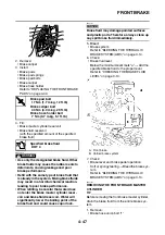
CHECKING THE REAR BRAKE DISC
1. Remove:
• Rear wheel
Refer to “REAR WHEEL” on page 4-31.
2. Check:
• Brake disc
Damage/galling
→
Replace.
3. Measure:
• Brake disc deflection
Out of specification
→
Correct the brake disc
deflection or replace the brake disc.
Refer to “CHECKING THE FRONT BRAKE
DISCS” on page 4-43.
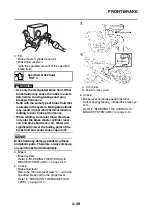
4. Measure:
• Brake disc thickness
Measure the brake disc thickness at a few dif-
ferent locations.
Out of specification
→
Replace.
Refer to “CHECKING THE FRONT BRAKE
DISCS” on page 4-43.
5. Adjust:
• Brake disc deflection
Refer to “CHECKING THE FRONT BRAKE
DISCS” on page 4-43.
6. Install:
• Rear wheel
Refer to “REAR WHEEL” on page 4-31.
EAS22580
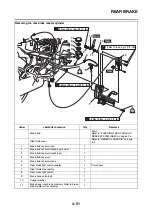
REPLACING THE REAR BRAKE PADS
TIP
When replacing the brake pads, it is not neces-
sary to disconnect the brake hose or disassem-
ble the brake caliper.
1. Measure:
• Brake pad wear limit “a”
Out of specification
→
Replace the brake
pads as a set.
2. Install:
• Brake pad springs
• Brake pad shims
(onto the brake pads)
• Brake pads
Brake disc deflection limit
0.15 mm (0.0059 in)
Brake disc thickness limit
4.5 mm (0.18 in)
T
R
.
.
Brake disc bolt
18 Nm (1.8 m·kg, 13 ft·lb)
LOCTITE®
Brake pad lining thickness (in-
ner)
6.3 mm (0.25 in)
Limit
0.8 mm (0.03 in)
Brake pad lining thickness (out-
er)
6.3 mm (0.25 in)
Limit
0.8 mm (0.03 in)
Summary of Contents for FJR1300A(D)
Page 1: ...2013 SERVICE MANUAL FJR1300A D 1MC 28197 E0 ...
Page 6: ......
Page 8: ......
Page 70: ...SPECIAL TOOLS 1 61 ...
Page 101: ...LUBRICATION POINTS AND LUBRICANT TYPES 2 30 ...
Page 104: ...LUBRICATION SYSTEM CHART AND DIAGRAMS 2 33 EAS20410 LUBRICATION DIAGRAMS 5 6 7 1 2 3 4 ...
Page 106: ...LUBRICATION SYSTEM CHART AND DIAGRAMS 2 35 1 3 2 ...
Page 107: ...LUBRICATION SYSTEM CHART AND DIAGRAMS 2 36 1 Main axle 2 Drive axle 3 Oil delivery pipe 1 ...
Page 108: ...LUBRICATION SYSTEM CHART AND DIAGRAMS 2 37 6 5 4 3 2 1 ...
Page 110: ...LUBRICATION SYSTEM CHART AND DIAGRAMS 2 39 1 2 3 4 5 6 7 8 9 ...
Page 112: ...LUBRICATION SYSTEM CHART AND DIAGRAMS 2 41 4 5 3 2 1 9 8 6 7 ...
Page 116: ...COOLING SYSTEM DIAGRAMS 2 45 7 1 2 3 4 5 5 8 9 6 8 9 10 11 12 ...
Page 124: ...CABLE ROUTING 2 53 Horn and radiator left side view A B 1 1 2 3 4 5 5 6 C 7 7 8 ...
Page 132: ...CABLE ROUTING 2 61 Rear fender top view 1 2 3 B C A B ...
Page 138: ...CABLE ROUTING 2 67 ...
Page 141: ......
Page 377: ...MIDDLE GEAR 5 76 Middle driven pinion gear shim Thickness mm 0 10 0 15 0 20 0 30 0 40 0 50 ...
Page 428: ...WATER PUMP 6 15 ...
Page 455: ...IGNITION SYSTEM 8 6 ...
Page 461: ...ELECTRIC STARTING SYSTEM 8 12 ...
Page 465: ...CHARGING SYSTEM 8 16 ...
Page 477: ...SIGNALING SYSTEM 8 28 ...
Page 533: ...FUEL INJECTION SYSTEM 8 84 ...
Page 551: ...CRUISE CONTROL SYSTEM 8 102 ...
Page 555: ...FUEL PUMP SYSTEM 8 106 ...
Page 563: ...ACCESSORY BOX SYSTEM 8 114 ...
Page 573: ...IMMOBILIZER SYSTEM 8 124 ...
Page 577: ...ABS ANTI LOCK BRAKE SYSTEM 8 128 ...
Page 616: ...ELECTRICAL COMPONENTS 8 167 7 1 3 2 18 21 20 19 9 11 12 13 14 15 16 17 6 8 4 5 10 ...
Page 658: ......
Page 659: ......
Page 660: ......