background image

8-

43

8

ROBOT LANGUAGE

8-5 Sample Programs

8-5-10 Palletizing for special pallets

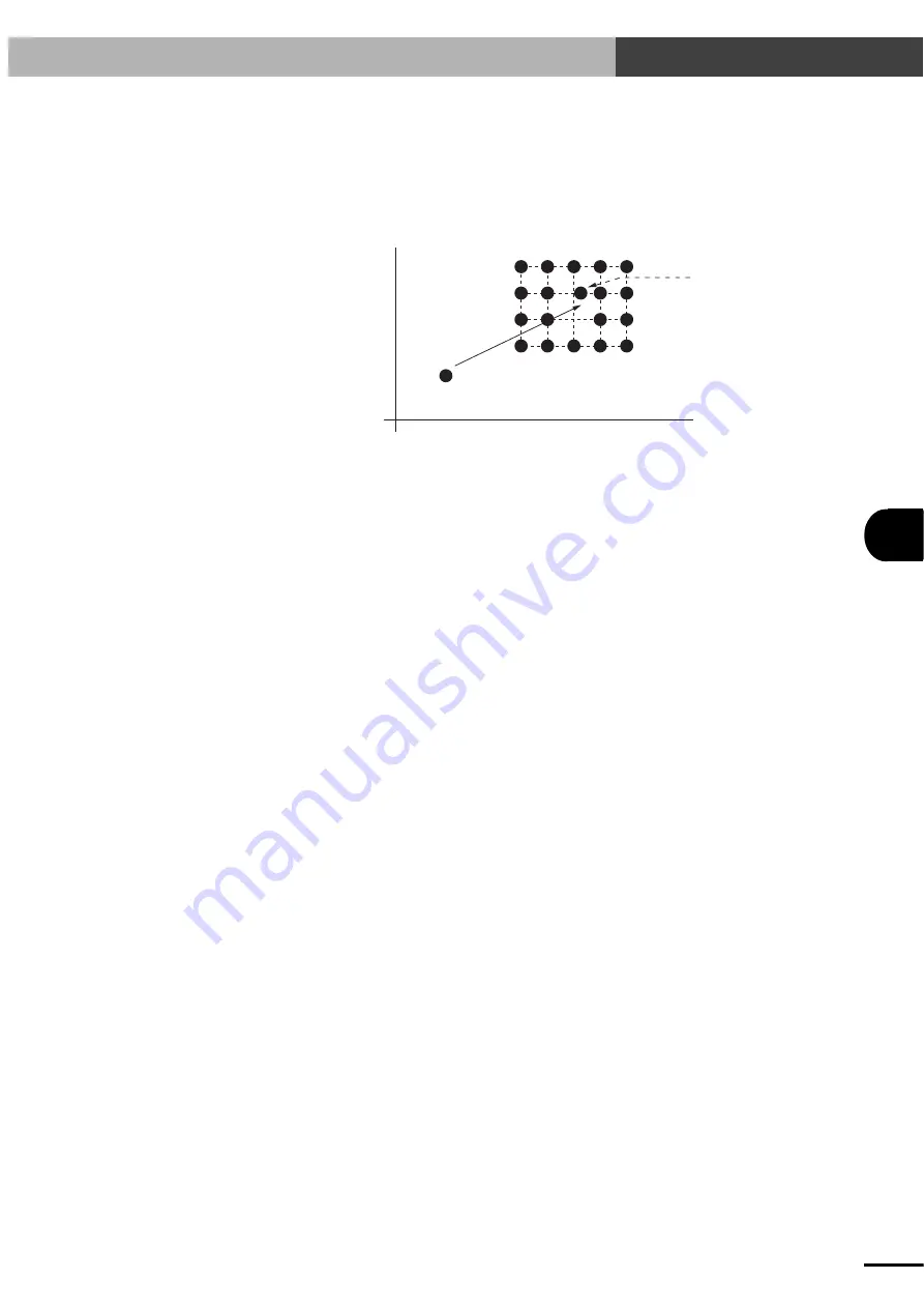
With this sample program, the robot picks up a workpiece supplied at P0 and place it sequentially on
a 4

×

5 pallet. However, the robot does not place a workpiece in the position at row 2 (from bottom),

column 3. Moreover, the position at row 3, column 3 is slightly shifted, so it should have data as a
different point (P1).

Point B (=P252)

Point C (=P253)

Point D (=P254)

Place points

Pick point

Point A (=P251)

P0

X

P1

Y

Teaching each point of P0, P1 and P251 to P254 should be completed beforehand in
PNT (point) mode. (Matrix is defined as pallet number 0 in this example.)

Program

Comment

[NO0]

001: MAT

4,

5,

0

; Defines 4

×

5 matrix as pallet number 0

002: C

1

; Sets counter variable to 1

003: L

0

; Label definition

004: JMPC

1,

8

; Jumps to L1 if counter variable is 8

005: MOVA

0,

100

; Moves to pick point

006: CALL

1,

1

; PICK routine call

007: JMPC

2,

13

; Jumps to L2 if counter variable is 13

008: MSEL

0

; Specifies movement matrix

009: MOVM

C,

100

; Moves to feed destination point (on pallet)

010: CALL

2,

1

; PLACE routine call

011: L

1

; Label definition

012: JMPC

3,

20

; Jumps to L3 if counter variable is 20

013: C+

; Counter variable increment

014: JMP

0,

0

; Jumps to L0

015: L

2

; Label definition

016: MOVA

1,

100

; Moves to position at row 3, column 3

017: CALL

2,

1

; PLACE routine call

018: JMP

1,

0

; Jumps to L1

019: L

3

; Label definition

Artisan Technology Group - Quality Instrumentation ... Guaranteed | (888) 88-SOURCE | www.artisantg.com

Summary of Contents for DRCX

Page 1: ... underutilized and idle equipment along with credit for buybacks and trade ins Custom engineering so your equipment works exactly as you specify Critical and expedited services Leasing Rentals Demos In stock Ready to ship TAR certified secure asset solutions Expert team I Trust guarantee I 100 satisfaction All trademarks brand names and brands appearing herein are the property of their respective ...

Page 2: ...User s Manual ENGLISH E YAMAHA 2 AXIS ROBOT CONTROLLER E67 Ver 5 04 DRCX Artisan Technology Group Quality Instrumentation Guaranteed 888 88 SOURCE www artisantg com ...

Page 3: ...Artisan Technology Group Quality Instrumentation Guaranteed 888 88 SOURCE www artisantg com ...

Page 4: ... Connector 2 8 2 7 Connecting to the Regenerative Unit 2 9 2 8 Connecting the Absolute Battery 2 10 Chapter 3 I O INTERFACE 3 1 3 1 I O Signals 3 2 3 2 Input Signal Description 3 3 3 2 1 Dedicated command input 3 3 3 2 2 General purpose input DI0 to DI15 3 6 3 2 3 SERVICE mode input SVCE 3 7 3 2 4 Interlock LOCK 3 7 3 2 5 Emergency stop inputs 1 2 EMG1 EMG2 3 7 3 3 Output Signal Description 3 8 3 ...

Page 5: ... 1 Robot language and point data 6 2 6 1 2 Using the TPB to enter the robot language 6 2 6 1 3 Program specifications 6 2 6 2 Editing Programs 6 3 6 2 1 Creating programs after initialization 6 4 6 2 2 Creating a new program 6 6 6 2 3 Adding a step 6 7 6 2 4 Correcting a step 6 9 6 2 5 Inserting a step 6 10 6 2 6 Deleting a step 6 11 6 3 Program Utility 6 12 6 3 1 Copying a program 6 12 6 3 2 Dele...

Page 6: ...et versus pallet using a SHIFT statement 8 42 8 5 10 Palletizing for special pallets 8 43 8 5 11 Changing the placement sequence for palletizing 8 44 8 5 12 Picking up workpieces from a 1 3 pallet conveyed by the conveyor and placing them on a 5 4 transfer pallet 8 45 8 5 13 Picking up 3 kinds of workpieces conveyed by the conveyor and placing them on the 3 3 3 4 4 4 transfer pallets while sorting...

Page 7: ...16 10 6 2 Loading data from a memory card 10 18 10 6 3 Formatting a memory card 10 20 10 6 4 Viewing the ID number for memory card data 10 22 10 7 Duty load factor monitor 10 23 10 7 1 Measuring the duty load factor 10 25 Chapter 11 COMMUNICATION WITH PC 11 1 11 1 Communication Parameter Specifications 11 2 11 2 Communication Cable Specifications 11 3 11 2 1 Connecting to the computer with a 25 pi...

Page 8: ...ing the System Backup Battery 14 3 14 3 Replacing the Absolute Battery 14 3 14 4 Updating the System 14 4 Chapter 15 SPECIFICATIONS 15 1 15 1 DRCX sereis 15 2 15 1 1 Basic specifications 15 2 15 1 2 Robot number list 15 3 15 1 3 LED display 15 4 15 1 4 Absolute Battery Unit 15 4 15 2 TPB 15 5 15 2 1 Basic specifications 15 5 15 3 Regenerative Unit RGU 2 15 6 15 3 1 Basic specifications 15 6 15 3 2...

Page 9: ...vi MEMO Artisan Technology Group Quality Instrumentation Guaranteed 888 88 SOURCE www artisantg com ...

Page 10: ...the DRCX controller performs positioning and pick and place tasks of various mechanical parts and devices This first chapter explains basic information you should know before using the DRCX controller such as names and functions of the various parts steps necessary to prepare the robot for operation and the architecture of the system itself Please read this chapter carefully for a basic overview o...

Page 11: ...ring the number of the robot to control and the payload parameter No troublesome servo adjustments are re quired The I O interface provides 16 input and 13 output points for general purpose user wiring as a standard feature as well as a 24V power supply for I O functions No additional power supply is required The TPB programming box option allows interactive user operation by simple menus that per...

Page 12: ... Installation Installing the controller 2 1 Wiring and connection Connecting the power supply 2 2 Grounding 2 3 Connecting peripheral equipment 2 4 to 2 8 Understanding the I O interface Chapter 3 Setting parameters Understanding basic TPB Chapter 4 operations Setting the various parameters Chapter 5 Programming Inputting or editing programs Chapter 6 Editing point data Chapter 7 Robot language Ch...

Page 13: ...t peripheral devices such as resolver origin sensor and brake signals 6 I O Connector This is used to connect external equipment such as a PLC 7 BAT Connector 1 2 This is the connector for the absolute battery 8 Motor Connector X Y This is the power line connector for the servo motor 9 Regenerative Unit Connector RGEN connector Some types of robots require connection to a regenerative unit In such...

Page 14: ...rnal View and Part Names Fig 1 1 Exterior of the DRCX controller 5 4 3 2 6 1 9 8 7 10 Fig 1 2 Three side view of the DRCX controller Artisan Technology Group Quality Instrumentation Guaranteed 888 88 SOURCE www artisantg com ...

Page 15: ... DRCX controller 5 DC Power Input Terminal Not used 6 Emergency Stop Button This is the emergency stop button When pressed it locks in the depressed position To release this button turn it clockwise To cancel emergency stop first release this button and then use the servo recovery command via the I O interface or the servo recovery operation from the TPB Fig 1 3 Exterior of the TPB TPB E M G Y A M...

Page 16: ...oducts to configure a robot system as shown below Y A M A H A M O T O R C O L T D DPB E M G Y A M A H A Fig 1 5 System configuration diagram TPB programming box IC memory card Printer Personal computer Dual axis robot DRCX Controller Gripper limit switches etc External control PLC and similar units Artisan Technology Group Quality Instrumentation Guaranteed 888 88 SOURCE www artisantg com ...

Page 17: ...ing options are available for the DRCX controller 1 TPB This is a hand held programming box that connects to the DRCX controller for teaching point data editing robot programs and operating the robot The TPB allows interactive user opera tion by simple menus so that even first time users can easily operate the robot with the TPB 2 IC memory card An IC memory card can be used with the TPB to back u...

Page 18: ...chapter contains precautions that should be observed when installing the controller as well as procedures and precautions for wiring the controller to the robot and to external equipment Artisan Technology Group Quality Instrumentation Guaranteed 888 88 SOURCE www artisantg com ...

Page 19: ...ntroller in locations with sufficient space at least 20mm away from the wall or other object for good ventilation and air flow Do not install the controller in locations where corrosive gases such as sulfuric acid or hydro chloric acid gas are present or in atmosphere containing flammable gases and liquids Install the controller in locations with a minimal amount of dust Avoid installing the contr...

Page 20: ...to 230V 10 AC100 to 115 200 to 230V 10 AC100 to 115 200 to 230V 10 AC200 to 230V 10 AC100 to 115 200 to 230V 10 AC200 to 230V 10 AC200 to 230V 10 c CAUTION If the power supply voltage drops below the above range during operation the alarm circuit will work and return the controller to the initial state the same as just after power on or stop operation To avoid this problem use a regulated power su...

Page 21: ...he correct specifications that will turn the power on or off to the entire system including the robot controller w WARNING Before beginning the wiring work make sure that the power supply for the entire system is turned off Doing the wiring work while power is still turned on may cause electrical shocks 2 2 3 Installing an external leakage breaker Since the robot controller drives the motors by PW...

Page 22: ... the power on off of the robot controller from an external device such as a PLC a current control switch contactor breaker etc may be used In this case the current control switch usually creates a large on off inrush current To minimize this on off inrush current surge killers must be installed for surge absorption Connect a surge killer in parallel with and close to each contact of the current co...

Page 23: ...DRCX to the Control Unit The DRCX controller can be operated either through the TPB programming box or through a PC personal computer equipped with an RS 232C terminal When using the TPB plug the TPB cable connector into the TPB connector of the DRCX controller Refer to 4 1 1 Connecting the TPB to the DRCX controller When using a PC plug the RS 232C interface cable connector 25 pins into the TPB c...

Page 24: ...Resolver excitation output 1 Resolver excitation output 1 Digital ground Digital ground Power supply 24V for origin sensor No connection Power supply 0V for origin sensor Origin sensor signal input 1 Power supply 0V for origin sensor Brake signal 1 Brake signal 1 Brake signal 1 Brake signal 1 Frame ground Resolver SIN input 2 Resolver SIN input 2 Resolver COS input 2 Resolver COS input 2 Resolver ...

Page 25: ... A c CAUTION Even if not using I O control the I O connector should be plugged in after completing the following wiring 1 Short pin numbers A24 EMG1 and B24 EMG2 2 Short pin numbers B4 LOCK and A15 or B15 0V 3 Short pin numbers A13 or B13 IN COM and A14 or B14 24V An external 24V power supply can also be connected to A13 or B13 IN COM instead of using the internal power supply If step 1 is not com...

Page 26: ...uch cases use the interconnection cable to connect the DRCX controller to the regenerative unit Fig 2 2 Connection of the DRCX controller to a regenerative unit Use the interconnection cable to make connections 2 7 Connecting to the Regenerative Unit Artisan Technology Group Quality Instrumentation Guaranteed 888 88 SOURCE www artisantg com ...

Page 27: ...hipped with the absolute battery disconnected an alarm is always issued when the controller is first turned on But this is not an equipment problem An alarm 23 ABS BAT L VOLTAGE might occur in some cases When the controller is first used or is kept turned off for a period in excess of the data backup time the battery must be recharged The battery is automatically charged while the controller is tu...

Page 28: ...zing the features of the DRCX series you must understand the signals assigned to each terminal on the I O connector and how they work This chapter covers this fundamental information This chapter also provides examples of I O circuit connections and timing charts for expanding the system by using a PLC or similar devices Refer to these diagrams and examples when creating sequence programs Terms ON...

Page 29: ...purpose input 3 General purpose input 4 General purpose input 5 General purpose input 6 General purpose input 7 General purpose input 8 General purpose input 9 General purpose input 10 General purpose input 11 General purpose input 12 General purpose input 13 General purpose input 14 General purpose input 15 SERVICE mode input External 24V power supply input for controller External 24V power suppl...

Page 30: ...ted command so other dedicated commands are ignored even if they are input When the LOCK signal is off no other commands can be accepted since an interlock is active One exception is the reset and servo recovery commands that can be executed even when the LOCK signal is off as long as the READY and BUSY signals meet the above condi tions A dedicated command input is accepted when the dedicated com...

Page 31: ...he robot does not move a relative distance from the stopped position by the interlock Similarly after a robot movement command is executed the controller still retains the target position data of that movement command as the current position data even if you move the robot to another position by manual operation When a relative movement command is executed under this condition the robot moves the ...

Page 32: ...e power will need to be turned off and back on again c CAUTION If return to origin must be repeated by the stroke end detection method wait at least 5 seconds before repeating it Servo recovery command SERVO After emergency stop releasing the emergency stop button and turning this input on closing the contact turns the servo power on so the robot is ready for restart As with other dedicated comman...

Page 33: ...2 Parameter Description Example of point number setting DI9 29 DI No Point No P0 P1 P3 P7 P15 P31 P63 P127 P254 P511 P999 OFF OFF OFF OFF OFF OFF OFF OFF OFF OFF ON DI8 28 OFF OFF OFF OFF OFF OFF OFF OFF OFF ON ON DI7 27 OFF OFF OFF OFF OFF OFF OFF OFF ON ON ON DI6 26 OFF OFF OFF OFF OFF OFF OFF ON ON ON ON DI5 25 OFF OFF OFF OFF OFF OFF ON ON ON ON ON DI4 24 OFF OFF OFF OFF OFF ON ON ON ON ON OFF...

Page 34: ... I O commands can be executed and also no programs and return to origin operation can be performed from the TPB or PC The only excep tions to this are the reset command and servo recovery command that can be executed regardless of whether the LOCK signal is on or off Leave this LOCK signal turned on contact closed during normal operation Once this LOCK signal is turned off contact open the robot r...

Page 35: ...on The BUSY signal turns off when command execution is complete At this point all the dedicated command inputs must be turned off contact open c CAUTION The dedicated command input must be a pulse input so that it is off when the BUSY signal turns on If the command input is left on the BUSY signal cannot turn off even after the command execution is complete As long as the BUSY signal is on the DRC...

Page 36: ...ams when connecting to external equipment such as a PLC 3 4 1 I O circuit specifications Input Circuit Excluding emergency stop input circuit Insulation method Photocoupler insulation Input terminal Relay contact or NPN open collector transistor connected between input terminal and 0V terminal Input response 30ms max Input current 5mA DC24V Input sensitivity Current on 3mA min Current off 1mA max ...

Page 37: ... controller depending on the sensor type Using such a sensor will cause erroneous operation Always check that the sensor meets the input signal specifications A large inrush current may flow depending on the output load If it exceeds the maximum output current of the internal power supply the protective circuit will work to turn off the output Keep the wires separated from the power lines of other...

Page 38: ...ransistor Incandescent lamp Solenoid valve Input signal Photocoupler Output signal DI DO DO DI IN COM 0V Controller side c CAUTION To prevent possible accidents when using an external 24V power supply do not use it simultaneously with the internal power supply Artisan Technology Group Quality Instrumentation Guaranteed 888 88 SOURCE www artisantg com ...

Page 39: ...USY READY LOAD LOAD LOAD LOAD LOAD LOAD LOAD A24 B24 B4 A3 B3 A2 B2 A1 B1 A4 B5 A6 B6 A7 B7 A8 B8 A16 B16 A17 B17 A18 B18 A19 B19 DC24V A13 B13 A14 B14 A15 B15 A5 A9 B9 A10 B10 A11 B11 A12 B12 DO 5 DO 6 DO 7 DO 8 DO 9 DO 10 DO 11 DO 12 LOAD LOAD LOAD LOAD LOAD LOAD LOAD LOAD A20 B20 A21 B21 A22 B22 A23 B23 LOAD DI 8 DI 9 DI 10 DI 11 DI 12 DI 13 DI 14 DI 15 General connections for internal 24V powe...

Page 40: ...E Y0F DC24V 0V Y10 Y11 Y12 Y13 Y14 Y15 Y16 Y17 Y18 DC24V 0V A5 B5 A6 B6 A7 B7 A8 B8 A9 B9 A10 B10 A11 B11 A12 B12 A4 B4 A3 B3 A2 B2 A1 B1 A24 B24 A13 B13 A15 B15 DI 0 DI 1 DI 2 DI 3 DI 4 DI 5 DI 6 DI 7 DI 8 DI 9 DI 10 DI 11 DI 12 DI 13 DI 14 DI 15 SERVO LOCK ORG S RESET AUTO R STEP R ABS PT INC PT EMG 1 EMG 2 IN COM 0V TB 1 2 R R R 3 4 5 6 7 8 9 10 11 12 13 14 15 16 17 18 19 20 21 22 23 24 25 26 2...

Page 41: ... supply Photocoupler Internal circuit X01 X00 X02 X03 X04 X05 X06 X07 DC24V X08 X09 X0A X0B X0C X0D X0E X0F DC24V B19 A19 B18 A16 B16 A17 B17 A18 A20 B20 A21 B21 A22 B22 A23 B23 TB 1 2 3 4 5 6 7 8 9 10 11 12 13 14 15 16 17 18 A13 B13 A15 B15 READY BUSY END DO 0 DO 1 DO 2 DO 3 DO 4 DO 5 DO 6 DO 7 DO 8 DO 9 DO 10 DO 11 DO 12 IN COM 0V R R Artisan Technology Group Quality Instrumentation Guaranteed 8...

Page 42: ...nal and also the servo turned on Robot is ready to operate in this state In contrast when the power is on while emergency stop is triggered the DRCX controller starts with the READY signal turned off under emergency stop conditions Robot operation is prohibited in this state To enable robot operation cancel the emergency stop to turn on the READY signal and then input a servo recovery command SERV...

Page 43: ...the dedicated command input Dedicated command BUSY END 30ms or less 1ms or less 1ms or less 1 At the rising edge of the dedicated command input the END signal turns off and the BUSY signal turns on 2 Turn off contact open the dedicated command input after checking that the BUSY signal turns on 3 Wait until the BUSY signal turns off 4 The END signal should be on when the BUSY signal turns off indic...

Page 44: ...urns off The BUSY signal immediately turns off since the com mand execution is already complete 4 The END signal should be on when the BUSY signal turns off indicating that the command has ended normally However the PRM20 system mode selection parameter bit 7 END output sequence setting at command execution completion setting can be changed so that the END signal turns on when the dedicated comman...

Page 45: ... emergency stop except for the reset RESET and servo recovery SERVO commands When a dedicated command input ABS PT INC PT AUTO R STEP R ORG S SERVO RESET was executed in SERVICE mode state Dedicated command 30ms or less 1ms or less 30ms or less END BUSY 1 At the rising edge of the dedicated command input the END signal turns off and the BUSY signal turns on 2 Turn off contact open the dedicated co...

Page 46: ...ed command Differs according to execution command END BUSY Command execution impossible 1 At the rising edge of the dedicated command input the END signal turns off and the BUSY signal turns on 2 Turn off contact open the dedicated command input after checking that the BUSY signal turns on 3 Wait until the BUSY signal turns off 4 The BUSY signal turns off since the command execution stops before c...

Page 47: ...ffers according to execution command When a interlock signal is input while a dedicated command is being executed the BUSY signal turns off The READY and END signals remain unchanged 3 6 I O Control Timing Charts Artisan Technology Group Quality Instrumentation Guaranteed 888 88 SOURCE www artisantg com ...

Page 48: ...s unchanged To enable robot operation cancel emergency stop to turn on the READY signal then input the servo recovery command SERVO 3 6 5 When alarm is issued READY END BUSY Alarm Dedicated command 5ms or less 1ms or less The READY BUSY and END signals all turn off Correct the problem while referring to 13 2 Alarm and Countermeasures 3 6 I O Control Timing Charts Artisan Technology Group Quality I...

Page 49: ...I0 to DI11 When specifying the robot axis the axis selection data should be input to DI13 and DI14 These input conditions should be kept unchanged until the BUSY signal turns on If these conditions are changed before the BUSY signal turns on then the data might be misrecognized 2 When a minimum of 30ms has elapsed input the point movement command ABS PT INC PT 3 At the rising edge of the dedicated...

Page 50: ...signment selection parameter setting Refer to the table on next page when you want to change the I O assignment After changing the I O assignment the DRCX controller must be restarted to enable the changes n NOTE The I O assignment change function is available on controllers whose version is 18 57 or later Artisan Technology Group Quality Instrumentation Guaranteed 888 88 SOURCE www artisantg com ...

Page 51: ...CE PO0 PO1 PO2 PO3 ORG O ZONE0 SRV O ZONE1 END BUSY READY CHG ORG S RESET SERVO LOCK PI0 PI1 PI2 PI3 PI4 PI5 2 2 SVCE PO0 PO1 PO2 PO3 PO4 PO5 END BUSY READY 0 Standard xx20 1 xx21 1 xx30 1 xx31 1 Type 3 Point teaching type Type 2 Point number output type Type 1 Type 0 Conven tional type 64 None No 16 4 No 64 None No 16 4 No I O assignment list 1 The PO output format varies depending on whether the...

Page 52: ... JOG For details on the ABS PT and INC PT commands see 3 2 1 Dedicated command input in this chapter The movement speed must be specified before running a point movement command or jog movement command See the table below to specify the movement speed Movement speed setting example SPD2 SPD1 OFF ON OFF ON Movement speed 100 PRM5 PRM6 PRM7 OFF OFF ON ON Jog movement direction command JOG Moves the ...

Page 53: ...pecifying the axis the DI13 and DI14 pin No B11 and A12 status must be checked beforehand Refer to the Jog movement JOG JOG timing chart in 3 7 3 Timing chart Point data write command PSET Writes the current position data in the specified point number To use this command the point number for writing the current position data must first be specified using a PI point number designation input input T...

Page 54: ...sition judgment parameter range selected by the PRM26 thousands digit value b Y axis position judgment parameter range selected by the PRM26 thousands digit value Target position point numbers for point movement commands ABS PT INC PT are output as binary values The same applies to point numbers which correspond to the point zone output function and the movement point zone output function The PO o...

Page 55: ...l I O PO200 to PO205 All PO outputs are reset OFF when a program reset is performed When using PO as an output signal that indicates the corresponding point number at the point zone output function The corresponding point number for the point zone output function is output to both the corresponding parallel I O PO0 to PO5 and the serial I O PO200 to PO205 All PO outputs are reset OFF when a progra...

Page 56: ... misrecognize the data 3 Turn on the JOG or JOG input signal while the CHG signal is on 4 The END signal turns off and the BUSY signal turns on indicating that the DRCX received the jog movement command 5 The robot moves in jog mode as long as the JOG or JOG input signal is on 6 Turn off the JOG or JOG input signal 7 Wait until the BUSY signal turns off 8 The BUSY signal turns off The END signal s...

Page 57: ...d depend on the I O assignment type Refer to the I O assignment list in 3 7 1 Changing the I O assignment The input status for designating the point number must be kept unchanged until step 3 is complete If this input status is changed the DRCX might misrecognize the data 2 After 30ms or more has elapsed turn on the PSET 3 The END signal turns off and the BUSY signal turns on indicating that the D...

Page 58: ...command execution q 1 To specify the movement axis input the axis designation data to DI13 and DI14 pin No B11 and A12 The input status specified here must be kept unchanged until step 3 is complete If this input status is changed the DRCX controller might misrecognize the data 2 Turn on the ABS PT or INC PT 3 The END signal turns off and the BUSY signal turns on indicating that the DRCX received ...

Page 59: ...PO0 to PO5 status does not change even after the robot has moved to P0 so no information is available to indicate whether the robot motion to P0 is complete or whether the movement command was received This should be kept in mind when moving the robot to point 0 When specifying the axis the DI13 and DI14 pin No B11 and A12 status must be checked beforehand Refer to PRM10 Control axis selection wit...

Page 60: ...ecify the movement axis input the axis designation data to DI13 and DI14 pin No B11 and A12 The input status specified here must be kept unchanged until step 3 is complete If this input status is changed the DRCX controller might misrecognize the data 2 Turn on the ABS PT or INC PT 3 The END signal turns off and the BUSY signal turns on indicating that the DRCX received the point movement command ...

Page 61: ... 0 This means that the PO0 to PO5 status does not change even after specifying P0 as the target position so no information is available to indicate whether the movement command to P0 was received This should be kept in mind when moving the robot to point 0 When specifying the axis the DI13 and DI14 pin No B11 and A12 status must be checked beforehand Refer to PRM10 Control axis selection with I O ...

Page 62: ...UT valid position 2 The Zone 0 and Zone 1 output signals are enabled and set to positive output by the Zone output selection parameter PRM24 1 Target position s point number outputs PO0 to PO3 are off since the current robot position is not within the point zone output range ZONE 0 and ZONE 1 output signals are also off since the robot does not yet enter the zone output range 2 Outputs the corresp...

Page 63: ... Y axis PRM93 c CAUTION When the current robot position is within two or more point zone output ranges the smaller or smallest point number is output Example If the current robot position is within two point output ranges specified by P2 and P5 then P2 is output If the current robot position is not within any point output range all of PO0 to PO5 turn off A 10ms sampling time is needed for position...

Page 64: ...t OUT valid position 2 The Zone 0 output signal is enabled and set to positive output by the Zone output selection parameter PRM24 3 Set the movement point as P6 1 Although the robot is within the P1 OUT valid position range point zone output range all the PO0 to PO3 target position point number outputs are off because P1 is not the movement point Moreover the ZONE 0 output is also off because the...

Page 65: ...is setting is specified by the PRM26 setting s thousands digit value The OUT valid position can be changed by parameter setting X axis PRM56 Y axis PRM96 The Positioning completed pulse can be changed parameter setting X axis PRM53 Y axis PRM93 c CAUTION All the PO0 to PO5 outputs are off when the robot is not within the point zone output range A 10ms sampling time is needed for position monitorin...

Page 66: ...e DRCX controller to edit or run programs for robot operation The TPB allows interactive user operation on the display screen so that even first time users can easily operate the robot with the TPB This chapter describes the basic operation of the TPB Artisan Technology Group Quality Instrumentation Guaranteed 888 88 SOURCE www artisantg com ...

Page 67: ... regardless of whether or not the ESC switch is held down c CAUTION Any of the messages 08 PNT DATA DESTROY 09 PRM DATA DESTROY or 10 PGM DATA DE STROY may appear on the TPB when the power to the controller is turned on See 13 2 Alarm and Counter measures If one of these messages appears turn off the power to the controller and then turn it back on again while the emergency stop button of the TPB ...

Page 68: ...le holding down the ESC switch on the front panel of the controller Failing to hold down the ESC switch will trigger emergency stop in the controller and turn off the servo When the TPB will be left disconnected from the controller for a long period of time we recommend attaching the RS 232C connector dust cover supplied to the TPB connector on the controller Artisan Technology Group Quality Instr...

Page 69: ... hierarchy A B C D To return to the previous screen or menu level press the ESC key See 4 4 Hierarchical Menu Structure in this chapter 3 If an error occurs during operation a buzzer sounds for approximately 1 second and an er ror message like that shown in Example E ap pears on the 3rd line of the screen If this hap pens check the contents of the error message and then press the ESC key The error...

Page 70: ... 1SPD 2RSET3CHG 4next 4 5 3 2 1 1 Current mode 2 Execution speed 3 No of task being executed 4 No of program being executed On TPB version 12 51 or later when switched from the lead program to another program this area shows the program numbers as the currently executed program lead program 5 No of step being executed 6 Current position left X axis right Y axis 4 3 2 Program edit screen EDIT PGM N...

Page 71: ...vement not possible 1 Unlocked state robot movement possible Return to origin command ORG S Reset command RESET Automatic operation start command AUTO R Step operation start command STEP R Absolute point movement command ABS PT Relative point movement command INC PT Servo recovery command SERVO 4 General purpose output From left DO12 to DO5 5 Dedicated and general purpose outputs From left READY B...

Page 72: ... X axis Y Y axis SPD Execution Speed Change RSET Program Reset CHG Program Change VAL Variable Monitor S_ON Servo ON CHGT Task Change MIO Memory IO Monitor normal Standard compati Compatible PGM Program PNT Point PRM Parameter ALL All Data normal Standard compati Compatible XY 2 axes FLIP Two single axis robots XY 2 axes FLIP Two single axis robots EDIT Editing OPRT Operation SYS System CARD Memor...

Page 73: ...point data editing manual release of brake and point trace movement to registered data point are prohibited The and keys can be used to move the robot and general purpose outputs can be controlled Any operation in EDIT mode is prohibited Cannot enter EDIT mode X Z X Z Operation Level 0 1 2 3 Description All operations are permitted Changing the execution speed and program is prohibited In addition...

Page 74: ...ohibited Cannot enter SYS B UP mode 4 5 2 Changing an access level 1 Press F3 SYS on the initial screen MENU select menu 1EDIT2OPRT3SYS 4MON SYS select menu 1SAFE2OPT 3UTL 4next SYS SAFE Password 18 11_ input password SYS SAFE select menu 1ACLV2SVCE 2 Press F4 next to switch the menu display and then press F1 SAFE 3 When the password entry screen appears enter the password and press 4 When the pas...

Page 75: ...n the change even after the controller power is turned off press F1 SAVE To save the change temporarily retain the change until the power is turned off press F2 CHG To cancel changing of the setting press F3 CANCEL 8 When writing is complete the screen returns to step 6 n NOTE The password is identical to the DRCX controller s version number For example if the controller version is 18 11 enter 18 ...

Page 76: ...f each of the parameters and explains how to use the TPB to change and specify parameter settings SAFETY Errors such as motor overload are detected by the software so the controller parameters must be set correctly to match the connected robot model The parameters are initialized to match the robot model when the robot is shipped so confirm them before starting use If there is any trouble please c...

Page 77: ...press F1 PRM 3 When editing the common parameters press F1 COM 4 The current PRM0 number of conditional in put points setting appears on the screen Use the STEP UP and STEP DOWN keys to scroll the parameters until you find the parameter you want to set 5 When the desired parameter is displayed enter the new value with the number keys and then press 6 When editing the X axis parameters press F2 X i...

Page 78: ...idden parameters See 10 5 1 Viewing hidden parameters Take extra caution when handling hidden parameters 5 2 1 Common parameters PRM0 No of conditional input points This parameter specifies the number of effective points for the third data conditional input for executing the JMPF statement of the robot language For example when the default setting is selected for this parameter the four points fro...

Page 79: ... OFF ON Alarm axis DO output Effective only when PRM1 2 Alarm axis X axis Y axis DO6 OFF ON For more details on the alarm No and contents refer to 13 2 2 Alarm message list PRM2 Operation at return to origin complete Selects the operation to be executed simultaneously with completion of return to origin A signal can be output as a general purpose output indicating that return to origin has been co...

Page 80: ...param eter specifies the jog speed at which the robot moves at a jog movement command JOG JOG This movement speed specified here is the speed used with DI10 turned ON and DI11 turned OFF When type 2 point number output type or type 3 point teaching type is selected by the I O assignment setting and the speed is changeable by SPD1 and SPD2 this parameter specifies the speed when SPD1 is set to ON a...

Page 81: ...to 3000 If this parameter is set to 30 then the jog speed will be 100 30 100 30mm sec PRM7 I O point movement command speed 3 This parameter specifies the movement speed at which the robot moves when a point movement command ABS PT INC PT is executed When type 3 point teaching type is selected by the I O assignment setting this param eter specifies the jog speed at which the robot moves at a jog m...

Page 82: ...set to 2 or 3 the program is reset only during automatic operation The program is not reset during step operation PRM10 Control axis selection with I O command This parameter determines whether to select an axis when a dedicated I O command ABS PT INC PT ORG S SERVO is executed If Type 3 Point teaching type is selected by the I O assignment change function this parameter also determines whether to...

Page 83: ...ing movement data 3 for TPB This parameter is used only by the TPB and is unavailable to users Input range 1 to 100 Default value 10 PRM16 Teaching count data written in TPB This parameter is used only by the TPB and is unavailable to users Default value 1 PRM17 Maximum program speed The speed data defined in MOVA MOVI and MOVM statements in a program is multi plied by this parameter value to dete...

Page 84: ...tem use END output sequence setting at command execution completion Reserved for system use Selected operating mode Normal mode DI0 to DI11 Conventional compatible mode DI0 to DI9 DRCA compatible output mode SRCA compatible output mode Normal mode to be output Conventional compatible mode not to be output Check No check Disable Enable ON at normal command completion ON at command signal OFF at nor...

Page 85: ... This selects whether to enable or disable the absolute backup function Normally this is set to enable and a battery for absolute backup is required If set to disable the controller can be operated without using an absolute backup bat tery When set to enable the robot position is maintained even after the power is turned off When set to disable however the origin position will be incomplete each t...

Page 86: ...s are available by setting for PRM24 The output logic can also be changed This parameter functions are allocated in bit units Input range 0 to 255 Default value 0 Function allocation in bit units Function Bit Bit Selected value Addition value 15 to 8 0 0 7 0 0 6 1 64 5 0 0 4 0 0 3 0 0 2 1 4 1 1 2 0 0 0 PRM24 64 4 2 70 0 1 2 3 4 5 6 7 8 to 15 Zone 0 output enable setting Zone 1 output enable settin...

Page 87: ...ION The zone output function does not work if one item of the point data is unspecified or return to origin is incomplete Example q DO0 OFF ON OFF Current position 100 00 50 00 200 00 100 00 PRM24 1 Zone 0 output enabled positive logic output P901 200 00 100 00 P900 100 00 50 00 DO2 ON OFF ON Current position Example w 100 00 50 00 200 00 100 00 PRM24 68 Zone 2 output enabled negative logic output...

Page 88: ...r position judgment parameter range 3 Movement point zone output supported in Ver 18 64 and later versions PO output occurs when the robot enters the position judg ment parameter range for the point data registered at the controller and which serves as the movement point data for the point movement command ABS PT INC PT e Point zone judgment method selection supported in Ver 18 64 and later versio...

Page 89: ...2 SVCE PO0 PO1 PO2 PO3 ORG O ZONE0 SRV O ZONE1 END BUSY READY CHG ORG S RESET SERVO LOCK PI0 PI1 PI2 PI3 PI4 PI5 2 2 SVCE PO0 PO1 PO2 PO3 PO4 PO5 END BUSY READY 0 Standard xx20 1 xx21 1 xx30 1 xx31 1 Type 3 Point teaching type Type 2 Point number output type Type 1 Type 0 Conven tional type 64 None No 16 4 No 64 None No 16 4 No I O assignment list 1 The PO output format varies depending on whether...

Page 90: ...speed for the robot so ensure that the correct payload is set If set too small abnormal vibration or overheat may occur resulting in troubles with the robot or controller Conversely if this parameter is larger than the actual payload a loss of the cycle time occurs which lowers productivity Input range Depends on robot type Units are in kilograms kg Default value 0 PRM50 can be specified only when...

Page 91: ...ard the target position The controller then determines that the positioning has been completed when the remaining distance to the target position is within this parameter setting However the robot contin ues moving until it reaches the target position even after the robot enters the positioning completed pulse range Since executing the next movement command is not allowed until the positioning is ...

Page 92: ...the range in which the controller determines that movement command is complete When a movement command is executed the robot moves toward the target position The controller then determines that the movement command has ended when the remaining distance to the target position is within this parameter setting The controller then initiates the subsequent step processing when the robot reaches this OU...

Page 93: ...erload alarm is issued when a current three times higher than the overload current PRM61 flows for a period of 3 seconds or an equivalent condition is detected Default value 240 PRM63 Current limit This sets the maximum motor input current Default value Depends on robot type PRM64 Maximum speed setting This parameter sets the maximum motor revolution speed Input range 1 to 4500 rpm Default value D...

Page 94: ...units in which point data is to be displayed It also specifies whether to enable the limitless movement function Input range 0 to 3 Meaning 0 mm millimeters limitless movement function disabled off 1 deg limitless movement function disabled off 2 mm millimeters limitless movement function enabled on 3 deg limitless movement function enabled on Default value Depends on robot type For more details s...

Page 95: ...osition is usually 0 specified value when the mark method is used If for some reason the origin position needs to be shifted by a particular amount then change this parameter For example if an unwanted position shift occurred then reteaching of all point data needs to be performed However the time and effort needed for this reteaching can be eliminated by setting the shift amount for this paramete...

Page 96: ...smaller value to reduce only the deceleration This parameter value can be changed in 1 steps with 100 equal to the value deter mined by PRM51 Input range 1 to 100 Default value 100 PRM82 Hold gain Available with Ver 18 50 or later Default value Depends on the robot PRM83 Not used Default value 0 PRM84 Not used Default value 0 PRM85 Not used Default value Depends on robot type c CAUTION Do not chan...

Page 97: ...ries enter the maximum payload Based on this parameter the controller determines the optimum acceleration speed for the robot so ensure that the correct payload is set If set too small abnormal vibration or overheat may occur resulting in troubles with the robot or controller Conversely if this parameter is larger than the actual payload a loss of the cycle time occurs which lowers productivity In...

Page 98: ...ard the target position The controller then determines that the positioning has been completed when the remaining distance to the target position is within this parameter setting However the robot contin ues moving until it reaches the target position even after the robot enters the positioning completed pulse range Since executing the next movement command is not allowed until the positioning is ...

Page 99: ...the range in which the controller determines that movement command is complete When a movement command is executed the robot moves toward the target position The controller then determines that the movement command has ended when the remaining distance to the target position is within this parameter setting The controller then initiates the subsequent step processing when the robot reaches this OU...

Page 100: ...load alarm is issued when a current three times higher than the overload current PRM101 flows for a period of 3 seconds or an equiva lent condition is detected Default value 240 PRM103 Current limit This sets the maximum motor input current Default value Depends on robot type PRM104 Maximum speed setting This parameter sets the maximum motor revolution speed Input range 1 to 4500 rpm Default value...

Page 101: ...e units in which point data is to be displayed It also specifies whether to enable the limitless movement function Input range 0 to 3 Meaning 0 mm millimeters limitless movement function disabled off 1 deg limitless movement function disabled off 2 mm millimeters limitless movement function enabled on 3 deg limitless movement function enabled on Default value Depends on robot type For more details...

Page 102: ...position is usually 0 specified value when the mark method is used If for some reason the origin position needs to be shifted by a particular amount then change this parameter For example if an unwanted position shift occurred then reteaching of all point data needs to be performed However the time and effort needed for this reteaching can be eliminated by setting the shift amount for this paramet...

Page 103: ...ller value to reduce only the deceleration This parameter value can be changed in 1 steps with 100 equal to the value deter mined by PRM91 Input range 1 to 100 Default value 100 PRM122 Hold gain Available with Ver 18 50 or later Default value Depends on the robot PRM123 Not used Default value 0 PRM124 Not used Default value 0 PRM125 Not used Default value Depends on robot type c CAUTION Do not cha...

Page 104: ...OGRAMMING In this chapter we will try programming some operations First you will learn how to enter a program using the TPB programming box Artisan Technology Group Quality Instrumentation Guaranteed 888 88 SOURCE www artisantg com ...

Page 105: ...eration so that the robot first moves to a position 50 5mm on the X axis then 21mm on theY axis from the origin point and then moves to another point 100mm on the X axis 200mm on theY axis away from that position just change the P0 point data to P0 50 50 21 00 6 1 2 Using the TPB to enter the robot language Robot language commands frequently used to create programs are printed on the lower part of...

Page 106: ...as already been created and stored Changing an existing program means correcting adding deleting or inserting steps in a program to change only part of it This section explains all the above program editing procedures and also describes how to view program information such as the number of steps left in a program Creating a program right after initialization 6 2 1 Creating a program right after in...

Page 107: ...e ESC key to reset the error A confir mation message then appears asking whether to create a new program as program No 0 To select and edit program No 0 press F1 yes To select and edit a program other than No 0 press F2 no 5 When you selected F2 no in step 4 enter the number of the program to be edited with the number keys and press The screen re turns to step 4 Make sure the program number is cor...

Page 108: ...all necessary operand data as needed EDIT PGM No 0 001 MOVA 0 100 point No 0 999 1P EDIT PGM No 0 001 MOVA 1 80_ speed 1 100 EDIT PGM No 0 001 MOVA 1 80 1MAT2MSEL3MOVM 4next 8 After entering the operand data press 9 When entry is completed correctly the cursor moves to the operation code part To edit the next step press STEP UP to scroll the step and repeat the procedure from step 6 Artisan Techno...

Page 109: ...no EDIT PGM No14 001 _ 1MAT2MSEL3MOVM 4next 2 Next press F1 PGM 3 The execution program number and step are displayed on the screen Press F4 CHG here 4 Enter the new program number with the number keys and press 5 A confirmation message appears Make sure the program number is correct and press F1 yes 6 Proceed with program editing by following step 6 onward in 6 2 1 Creating programs after ini tia...

Page 110: ...0 EDIT PGM No10 050 WAIT 3 1 1MOD 2INS 3DEL 4CHG EDIT select menu 1PGM 2PNT 3UTL 2 Next press F1 PGM 3 The execution program number and step are displayed on the screen Press F4 CHG here 4 Enter the program number you want to edit with the number keys and press 5 Enter the last step number with the number keys and press 6 When the last step is displayed press STEP UP Artisan Technology Group Quali...

Page 111: ...1 _ 1MAT2MSEL3MOVM 4next 8 After selecting the robot language command enter the operand data When you press X Z the cursor moves to op erand 1 so enter the data with the number keys Do not press at this point While pressing X Z or X Z to move the cur sor enter all necessary operand data as needed 9 After entering the operand data press 10 When the program has been edited correctly the screen retur...

Page 112: ... mand shown on the lower part of each number key To change the robot language menu display press F4 next To go back to the previous menu display press the BS key 5 After selecting the robot language command enter the operand data When you press X Z the cursor moves to op erand 1 so enter the data with the number keys Do not press at this point While pressing X Z or X Z to move the cur sor enter al...

Page 113: ...CHG 3 Press F2 INS 4 Select F1 to F3 or a robot language com mand shown on the lower part of each number key To change the robot language menu display press F4 next To go back to the previous menu display press the BS key 5 After selecting the robot language command enter the operand data When you press X Z the cursor moves to op erand 1 so enter the data with the number keys Do not press at this ...

Page 114: ..._ REG steps 50 EDIT PGM No10 010 MOVA 999 100 1MOD 2INS 3DEL 4CHG EDIT PGM No10 010 MOVA 999 100 delete OK 1yes 2no EDIT PGM No10 010 WAIT 3 1 1MOD 2INS 3DEL 4CHG 3 Press F3 DEL 4 A confirmation message appears To delete the step press F1 yes To cancel the deletion press F2 no 5 When the step has been deleted the screen re turns to step 3 Artisan Technology Group Quality Instrumentation Guaranteed...

Page 115: ...OPY2DEL 3LIST EDIT UTL COPY Copy from No _ Program No 0 99 EDIT UTL COPY Copy from No 0 Copy to No 99_ Program No 0 99 2 Next press F3 UTL 3 Press F1 COPY 4 Enter the program number you want to copy from with the number keys and then press 5 Enter the program number you want to copy to with the number keys and then press Artisan Technology Group Quality Instrumentation Guaranteed 888 88 SOURCE www...

Page 116: ... up to step 2 in 6 3 1 Copying a program 2 Press F2 DEL EDIT UTL select menu 1COPY2DEL 3LIST EDIT UTL DEL delete PGM No _ Program No 0 99 EDIT UTL DEL delete PGM No 22 delete OK 1yes 2no EDIT UTL select menu 1COPY2DEL 3LIST 3 Enter the number of the program you want to delete with the number keys and press 4 A confirmation message appears asking whether to delete the selected program To delete the...

Page 117: ...r of available remaining steps To view other program information press the STEP UP and STEP DOWN keys to scroll the screen 4 Press the ESC key to return to the screen of step 2 In addition to the number of existing steps the steps equivalent to the number of programs are used internally as the program control steps For example if two programs are registered and their respective 50 and 100 steps ar...

Page 118: ... allows you to directly enter point data with the TPB number keys Teaching playback moves the robot in manual operation to a desired position and then obtains that position as point data Direct teaching is basically the same as teaching playback except that you move the robot by hand Artisan Technology Group Quality Instrumentation Guaranteed 888 88 SOURCE www artisantg com ...

Page 119: ...ss F1 MDI 4 The currently selected X axis point data in the execution program is displayed on the screen If you want to edit another point data press the STEP UP and STEP DOWN keys to scroll the point data To directly select the point data press F1 CHG 5 Enter the point number you want to edit with the number keys and press 6 Enter the point data with the number keys To edit the Y axis data press ...

Page 120: ...0 P0 X 0 00 mm 0 00 0 00 1CHG 2DO 3Y 4next 2 Next press F2 PNT 3 Press F2 TCH 4 The currently selected point data in the execu tion program appears on the screen If you want to edit another point data press the STEP UP and STEP DOWN keys to scroll the point data To directly select the point data press F1 CHG 5 Enter the point number you want to edit with the number keys and press Artisan Technolog...

Page 121: ... SPEED 2 and SPEED 3 are selectable as the teaching movement data After pressing F4 next each time F1 SPD is pressed the settings change in the order of 1 2 3 1 To change the teaching movement data setting press F4 next and then press F2 S_SET Then enter the desired speed with the number keys and press The screen returns to step 6 when the speed parameter has been changed correctly 8 Move the robo...

Page 122: ...CH 3DTCH4DEL 2 Next press F2 PNT 3 Press F3 DTCH 4 Following the message press the emergency stop button on the TPB 5 The currently selected X axis point data in the execution program is displayed on the screen If you want to edit another point data press the STEP UP and STEP DOWN keys to scroll the point data To directly select the point data press F1 CHG 6 Enter the point number you want to edit...

Page 123: ...e key The current position is input as point data When registering again the point which is al ready registered the axis selection screen ap pears To register both X andY axes press F1 XY To register the X axis only press F2 X To register the Y axis only press F3 Y 9 The screen will return to step 7 and the current position will be input as the point data When all points have been edited in the sa...

Page 124: ...ching The following steps are explained using the teaching playback screen 2 When the robot reaches the point where you want to use a general purpose output tempo rarily stop the operation and press F2 DO EDIT PNT TCH 1 50 P0 X 0 00 mm 0 00 0 00 1CHG 2DO 3Y 4next EDIT PNT TCH 1 50 DO 0 0 DO 1 0 DO 2 0 DO 3 0 DO 4 0 DO 5 0 1DO0 2DO1 3DO2 4next EDIT PNT TCH 1 50 P0 X 0 00 mm 0 00 0 00 1CHG 2DO 3Y 4n...

Page 125: ...0 0 00 1BRK 2PLT 3Y 4next EDIT PNT DTCH select axis for brake control 1ALL 2X 3Y EDIT PNT DTCH P0 X 0 00 mm 0 00 0 00 1BRK 2PLT 3Y 4next 3 The axis selection screen appears to release the brake To release the brakes on all axes press F1 ALL To release the brake on the X axis only press F2 X To release the brake on the Y axis only press F3 Y 4 A confirmation message appears asking whether to releas...

Page 126: ...K 1yes 2no EDIT PNT select menu 1MDI 2TCH 3DTCH4DEL 3 Enter the point number at the start to delete point data with the number keys and press 4 Enter the point number at the end to delete point data with the number keys and press 5 A confirmation message appears asking whether to delete the data To delete the data press F1 yes To cancel the deletion press F2 no 6 When the point data has been delet...

Page 127: ... using the manual data input screen 2 In the case of manual data input press F2 PLT In the case of teaching playback or direct teach ing press F4 next to change the function display then press F2 PLT EDIT PNT MDI P0 X 0 00 mm 0 00 0 00 1CHG 2PLT EDIT PNT MDI input pallet No _ pallet No O 31 EDIT PNT MDI P251 X mm _ 1CHG 2PLT 3 Enter the desired pallet number with number keys and then press 4 The s...

Page 128: ...o move in the X axis direction only press F2 X To move in the Y axis direction only press F3 Y The movement speed will be 10 of the value speed parameter displayed on the upper right of the screen 4 A confirmation message appears To move the robot press F1 yes To cancel moving the robot press F2 no 5 When the movement is completed the screen returns to step 2 c CAUTION When the SERVICE mode functi...

Page 129: ...7 12 MEMO Artisan Technology Group Quality Instrumentation Guaranteed 888 88 SOURCE www artisantg com ...

Page 130: ... complex robot and peripheral device movements This robot language is an upper version of the DRC DRCA and DRCH series robot language but fully compatible with it so that the previous programs used with these conventional controllers can be easily upgraded At the beginning of this chapter you will find a convenient table of robot language commands At the end of this chapter sample programs are lis...

Page 131: ...d pallet work position on matrix MOVM pallet work position maximum speed Jumps to a specified label when counter array variable C equals the specified value JMPC label number counter value Jumps to a specified label when counter variable D equals the specified value JMPD label number counter value Specifies the array element of counter array variable C CSEL array element number Defines counter arr...

Page 132: ... automatically converts the input characters to upper case One command statement must be described within one line It cannot be written over multiple lines Multiple command statements cannot be described on one line Up to 80 one byte char acters including carriage line return can be described on one line One or more spaces must be inserted between the operation code and the operand Operands enclos...

Page 133: ...am Memory I O from 100 to 131 can be freely turned on or off by the user or their values can be referenced However outputs 132 to 147 are controlled by the system so the user can only refer to their values Memory I O description Type General purpose Dedicated Meaning Memory I O available to the user The user can freely set this with a DO statement Task 0 main task status Always set to 1 Task 1 sta...

Page 134: ...ollowing relation The following data is independent of each task Point variable P coordinate shift amount specified with the SHFT command definition amount of arch motion element designation of the counter array variable C specified with the CSEL com mand and pallet designation number specified with the MSEL command The following data is shared with each task Point data general purpose input gener...

Page 135: ... specified the robot moves in the direction of shorter distance For example when just 30mm is specified for the point setting the movement direction differs depending on the current position However when 5030mm is specified the robot always moves in the direction opposite the return to origin direction In contrast when 5030mm is specified the robot always moves in the same direction as when perfor...

Page 136: ...mand such as MOVI which specifies the amount of movement the movement direction is determined by the plus minus sign of point data just as with normal move ment c CAUTION The maximum distance of one movement is a distance equal to one cycle 360 To move a distance longer than one cycle divide the movement distance into two or more portions In limitless movement XINC XDEC or YINC YDEC allows moving ...

Page 137: ...tion speed in OPRT mode is 100 then 100 will be equal to 3000 rpm when PRM64 and PRM104 3000 8 4 2 MOVI Function Moves a distance specified by a point number from the current position Format MOVI point number maximum speed Example MOVI 10 80 Moves an amount equal to point data P10 from the current position at speed 80 Explanation This command moves the robot on the relative coordinates with the cu...

Page 138: ...e P statement is set as the point number See 8 4 12 P 2 DI number Specify one of the 16 0 to 15 general purpose inputs 3 DI status 1 means on and 0 means off Other The robot speed during execution of the MOVF movement can be specified by PRM4 Refer to PRM4 MOVF speed Note that this will not be affected by the OPRT mode execution speed 8 4 4 JMP Function Jumps to a specified step in a specified pro...

Page 139: ...s input condition value a jump is executed The number of points that can be branched under the input condition depends on the number of conditional input points which is set with PRM0 See PRM0 No of conditional input points c CAUTION Select a number of conditional input points that is large enough to accommodate the actual number of input conditions to be used If an error is made in setting the nu...

Page 140: ... indicates the destination to jump Any number from 0 to 255 can be specified See 8 4 7 L 2 DI or MI number Specify one of the general purpose input numbers from 0 to 15 16 points or memory input numbers from 100 to 147 48 points 3 Input status 1 means on and 0 means off 8 4 7 L Function Defines the jump destination for JMP JMPF or JMPB statements etc Format L label number Example L 100 Defines lab...

Page 141: ...he step following the CALL statement in the main program An error occurs and program execution stops if the program being executed is called by the CALL statement Even when the program number is changed by the CALL statement resetting it will return to the original program number when program execution begins An error stack overflow might occur if a jump is made to another program by the JMP or JM...

Page 142: ...put numbers from 0 to 15 16 points or memory input numbers from 100 to 147 48 points 2 Input status 1 means on and 0 means off 8 4 11 TIMR Function Waits for a specified amount of time before advancing to the next step Format TIMR time Example TIMR 100 Moves to the next step after waiting one second Explanation This command is used when adjusting the time within the program Time may be specified i...

Page 143: ...t or when the pro gram reset is applied for example by switching the execution program the point variable P will be initialized to 0 Point variables P in a task are independent of those in other tasks For example the definition and edited contents of a point variable used in task 1 do not affect the point variable used in task 0 8 4 13 P Function Adds 1 to a point variable P Format P Example P Add...

Page 144: ...g is omitted all axes are selected 8 4 16 STOP Function Temporarily interrupts program execution Format STOP Example STOP Temporarily interrupts program execution Explanation This command temporarily interrupts execution of a program If two or more tasks are being executed then all those tasks are interrupted This command can be used at any point in a program The next execution will restart from t...

Page 145: ...ons of the 4 corners in PNT point mode to create point data the point numbers are generally specified as follows If pallet number is n for instance enter the position of the reference point row 1 col umn 1 in p 251 4n the position at the end of row 1 in p 252 4n the position at the end of column 1 in p 253 4n and the position of the remaining corner in p 254 4n To define a one dimension matrix suc...

Page 146: ...command selects a matrix and is always used with a MOVM state ment as a pair 1 Pallet number This number is used for matrix identification and can be set from 0 to 31 Others The pallet number assigned with the MSEL statement is independent of each task For example when different pallet numbers are assigned to task 0 and task 1 then task 0 and task 1 execute the MOVM state ment based on different p...

Page 147: ...xample on a row M column N matrix the pallet work position at row A col umn B is found by A 1 N B When a character C or D is entered here for special use a counter variable is set in each pallet work position 2 Maximum speed The maximum speed can be set to any level between 1 and 100 If the execution speed in OPRT mode is 100 then 100 will be equal to 3000 rpm when PRM64 and PRM104 3000 Others The...

Page 148: ...ment and indicates the destination to jump Any number from 0 to 255 can be specified See 8 4 7 L 2 Counter value Set any value from 0 to 65535 8 4 21 JMPD Function Jumps to a specified label when the counter variable D matches a speci fied value Format JMPD label number counter value Example JMPD 5 100 Jumps to label 5 when the counter variable D is 100 Program execution proceeds to the next step ...

Page 149: ...ized to 0 The element number designated with the CSEL statement is independ ent of each task For example when different array elements are des ignated for task 0 and task 1 the definition or change in the counter array variable C of task 1 does not affect task 0 8 4 23 C Function Sets the counter array variable C Format C counter value Example C 200 Sets the counter array variable C to 200 Explana...

Page 150: ...ied value from the counter array vari able C specified with the CSEL statement The subtraction value can be set to any value from 1 to 65535 If the subtraction value is omitted then 1 is subtracted from the counter array variable C 8 4 26 D Function Sets the counter variable D Format D counter value Example D 200 Sets the counter variable D to 200 Explanation The counter variable D can be set to a...

Page 151: ...value is omitted then 1 is added to the counter variable D 8 4 28 D Function Subtracts a specified value from the counter variable D Format D subtraction value Example D 100 Subtracts 100 from the counter variable D D D 100 D Subtracts 1 from the counter variable D D D 1 Explanation This command subtracts a specified value from the counter variable D The subtraction value can be set to any value f...

Page 152: ...and the search method for the other axis then return to origin on the axis using the mark method must first be completed before performing return to origin on the axis using the search method Use the TPB to perform return to origin on the axis using the mark method Once return to origin is performed after the robot cable and absolute battery are connected there is no need to repeat it even when th...

Page 153: ...performs an arch motion 1 for the X axis and 2 for the Y axis 2 Position This is the position absolute position with respect to the origin the arch motion axis moves to The setting range is from 9999 to 9999 mm Others The arch s arc size can be set with the arch position parameters PRM57 PRM97 If an ACHA statement is executed independently the subsequent movement commands MOVA MOVI or MOVM stateme...

Page 154: ... arch motion 1 for the X axis and 2 for the Y axis 2 Distance This is the distance relative distance with respect to the current position the arch motion axis moves The setting range is from 9999 to 9999 mm Others The arch s arc size can be set with the arch position parameters PRM57 PRM97 If an ACHI statement is executed independently the subsequent movement commands MOVA MOVI or MOVM statements ...

Page 155: ...lid position 1 Axis Specify the axis to be moved 1 for the X axis and 2 for the Y axis 2 Point number The point number is a number assigned to each point from 0 to 999 1000 points and used to create point data in point mode When a character P is entered here for special use a point variable defined by the P statement is set as the point number Refer to 8 4 12 P 3 Maximum speed The maximum speed ca...

Page 156: ... the axis reaches the OUT valid position 1 Axis Specify the axis to be moved 1 for the X axis and 2 for the Y axis 2 Point number The point number is a number assigned to each point from 0 to 999 1000 points and used to create point data in point mode When a character P is entered here for special use a point variable defined by the P statement is set as the point number Refer to 8 4 12 P 3 Maximu...

Page 157: ...character P is entered here for special use a point variable defined by the P statement is set as the point number Refer to 8 4 12 P Others When the program is reset or when the program reset is applied by switching the execution program the shift data will be initialized to 0 00 0 00 The SHFT statement affects MOVA MOVF MOVM DRVA ACHA MOVL and MOVC but does not affect MOVI DRVI and ACHI The coord...

Page 158: ...k Set to 0 when executing a new task and set to 1 when restarting a suspended task Others A task number which is being executed cannot be specified A task number which has been suspended can be specified The task terminates when the last step is detected When a subtask terminates it does not affect operation of other tasks But if task 0 main task terminates all other tasks in operation also termin...

Page 159: ...mparison condition and the tens represent the Y axis comparison condition When set to 1 this establishes the condition that the robot should be closer to the origin than the specified position When set to 2 this establishes the condition that the robot should be farther away from the origin than the specified position In the case of 0 the conditions are met whether the robot is posi tioned on eith...

Page 160: ...t and MOVC statement are consecutively written The MOVL and MOVC statements execute advanced reading execute the steps that follow interpolation motion Therefore to issue the DO output after the end point of the interpolation motion is reached the DO statement should be written after the MOVA statement following the MOVL and MOVC statements In this case set the specified point for MOVA to the same...

Page 161: ...100 100 steps When the execution speed in OPRT mode is 100 then 100 will be equal to a speed of 1000mm s when PRM64 and PRM104 are set to 3000 and the ball screw lead is 20mm 3 Locus type Select the locus type 0 for the circular segment locus and 1 for the circular locus Others The movable radius is 1000mm maximum and 2mm minimum The robot does not stop and continues operating when the MOVL state ...

Page 162: ... 50mm 50mm 50mm 50mm P0 P1 Start position Movement distance 50mm Point Program Comment NO0 001 L 0 Label definition 002 MOVA 0 100 Moves to P0 003 MOVI 1 100 Moves five times at a 50mm pitch 004 MOVI 1 100 Moves five times at a 50mm pitch 005 MOVI 1 100 Moves five times at a 50mm pitch 006 MOVI 1 100 Moves five times at a 50mm pitch 007 MOVI 1 100 Moves five times at a 50mm pitch 008 JMP 0 0 Retur...

Page 163: ...command 1 Output 0 Canceled General purpose output P1 P2 Job 1 Job 2 Program Comment NO0 001 DO 1 0 Cancels job 1 command 002 DO 2 0 Cancels job 2 command 003 L 1 Label definition 004 MOVA 1 100 Moves to P1 005 DO 1 1 Outputs job 1 command 006 WAIT 1 1 Waits until job 1 is complete 007 DO 1 0 Cancels job 1 command 008 MOVA 2 100 Moves to P2 009 DO 2 1 Outputs job 2 command 010 WAIT 2 1 Waits until...

Page 164: ...ervo Air cylinder DO0 Air chuck DO1 Upper end limit switch DI0 Lower end limit switch DI1 Workpiece detection sensor DI2 Program Comment NO1 001 L 1 Label definition 002 MOVA 0 100 Moves to the standby position 003 WAIT 2 1 Waits for workpiece feed 004 MOVA 1 100 Moves to the workpiece feed position 005 DO 0 1 Air cylinder moves down 006 WAIT 1 1 Waits until the air cylinder moves down 007 DO 1 1 ...

Page 165: ...unt position on the 1st rear conveyor Workpiece mount position on the 2nd rear conveyor Workpiece mount position on the 3rd rear conveyor Workpiece mount position on the 4th rear conveyor Workpiece mount position on the 5th rear conveyor Point Operation q Moves to the workpiece feed position and picks up a workpiece w Moves to the workpiece mount position and places the workpiece P0 P1 P2 P3 P4 P5...

Page 166: ... to the workpiece feed position 002 DO 0 1 Air cylinder moves down 003 WAIT 1 1 Waits until the air cylinder moves down 004 DO 1 1 Chuck closes 005 TIMR 100 Stays for one second 006 DO 0 0 Air cylinder moves up 007 WAIT 0 1 Waits until the air cylinder moves up NO4 Placing a workpiece 001 MOVA P 100 Moves to the workpiece mount position 002 DO 0 1 Air cylinder moves down 003 WAIT 1 1 Waits until t...

Page 167: ...ral purpose input output points DI8 and DO0 in this case one at a time and perform the handshake This is for synchronizing the DRCX controller program with an external device such as a PLC If this part is omitted the wrong program might be selected during program selection with the JMPF statement In specific operations an external device should turn on DI8 after confirming DI3 to DI0 The DRCX cont...

Page 168: ...s 9 015 JMPF 1 11 10 Jumps to L1 of NO11 when input is 10 016 JMPF 1 12 11 Jumps to L1 of NO12 when input is 11 017 JMPF 1 13 12 Jumps to L1 of NO13 when input is 12 018 JMPF 1 14 13 Jumps to L1 of NO14 when input is 13 019 JMPF 1 15 14 Jumps to L1 of NO15 when input is 14 020 JMPF 1 16 15 Jumps to L1 of NO16 when input is 15 021 JMP 0 0 Returns to L0 of program NO0 NO1 001 L 1 Label definition 00...

Page 169: ...254 should be completed beforehand in PNT point mode Matrix is defined as pallet number 0 in this example Program Comment NO0 001 MAT 4 5 0 Defines a 4 5 matrix as number 0 002 C 1 Sets counter variable to 1 003 L 0 Label definition 004 MOVA 0 100 Moves to pick point at speed 100 005 CALL 1 1 PICK routine call 006 MSEL 0 Specifies movement matrix 007 MOVM C 50 Moves to place point on pallet at spe...

Page 170: ...ransport pallet as pallet number 1 in this example Program Comment NO0 001 MAT 4 5 0 4 5 matrix definition for supply pallet 002 MAT 4 5 1 4 5 matrix definition for transfer pallet 003 C 1 Sets counter variable to 1 004 L 0 Label definition 005 MSEL 0 Matrix selection for feed pallet 006 MOVM C 100 Moves to supply pallet 007 CALL 1 1 PICK routine call 008 MOVA 0 100 Moves to processing position 00...

Page 171: ... 0 00 P0 is the amount of shift to the supply pallet and P1 is the amount of shift to the destination pallet Program Comment NO0 001 MAT 4 5 0 Defines 4 5 matrix as pallet number 0 002 MSEL 0 Specifies movement matrix 003 C 1 Sets counter variable to 1 004 L 0 Label definition 005 SHFT 0 Sets pick point shift 006 MOVM C 100 Moves to pick point on pallet at speed 100 007 CALL 1 1 PICK routine call ...

Page 172: ...s example Program Comment NO0 001 MAT 4 5 0 Defines 4 5 matrix as pallet number 0 002 C 1 Sets counter variable to 1 003 L 0 Label definition 004 JMPC 1 8 Jumps to L1 if counter variable is 8 005 MOVA 0 100 Moves to pick point 006 CALL 1 1 PICK routine call 007 JMPC 2 13 Jumps to L2 if counter variable is 13 008 MSEL 0 Specifies movement matrix 009 MOVM C 100 Moves to feed destination point on pal...

Page 173: ...1 five times 004 C 10 Sets counter variable to 10 005 CALL 2 5 Calls subroutine NO2 five times 006 C 11 Sets counter variable to 11 007 CALL 1 5 Calls subroutine NO1 five times 008 C 20 Sets counter variable to 20 009 CALL 2 5 Calls subroutine NO2 five times NO1 Execution while counting up 001 MOVA 0 100 Moves to pick point 002 CALL 3 1 PICK routine call 003 MSEL 0 Specifies movement matrix 004 MO...

Page 174: ...pallet number 0 and transport pallet as pallet number 1 in this example Since the supply pallet is a one dimensional matrix input of P253 and P254 is not necessary N N Y Y N N Y Y Start Pallet definition Initialization of variables Supply pallet routine call Transport pallet routine call Supply pallet routine Pallet set Move to supply pallet and pick up workpiece Variable C 3 C C 1 Eject pallet C ...

Page 175: ...s to L1 if counter variable C is 3 006 C Counter variable C increment 007 JMP 2 1 Jumps to L2 008 L 1 Label definition 009 CALL 5 1 Supply pallet eject routine call 010 C 1 Initializes counter variable C to 1 011 L 2 Label definition NO2 Transfer pallet routine 001 WAIT 1 1 Waits until transfer pallet is set 002 MSEL 1 Selects transport pallet matrix 003 MOVM D 100 Moves to transport pallet 004 CA...

Page 176: ...ce A 002 MAT 3 4 1 Defines 3 4 matrix for workpiece B 003 MAT 4 4 2 Defines 4 4 matrix for workpiece C 004 CSEL 0 Sets array element of counter array variable C to 0 005 C 1 Sets counter array variable C 0 to 1 006 CSEL 1 Sets array element of counter array variable C to 1 007 C 1 Sets counter array variable C 1 to 1 008 CSEL 2 Sets array element of counter array variable C to 2 009 C 1 Sets count...

Page 177: ...0 Moves to workpiece B pallet 005 CALL 6 1 PLACE routine call 006 JMPC 1 12 Jumps to L1 if C 1 is 12 007 C Counter array variable C 1 increment 008 JMP 2 2 Jumps to L2 009 L 1 Label definition 010 CALL 8 1 Eject routine call for workpiece B pallet 011 C 1 Initializes counter array variable C 1 to 1 012 L 2 Label definition NO3 Transfer routine for workpiece C 001 WAIT 6 1 Waits until workpiece C p...

Page 178: ... PNT point mode Supply pallet is defined as pallet 0 and smaller pallets as pallets 1 and 2 in this example Start Variable D 12 Pallet definition Variable D 12 Initialization of variables Move to supply pallet and pick up workpiece Move to smaller pallet 1 and place workpiece Move to supply pallet and pick up workpiece Move to smaller pallet 2 and place workpiece End C For workpiece pickup count D...

Page 179: ...1 12 Jumps to L1 if counter variable D is 12 014 C Counter variable C increment 015 D Counter variable D increment 016 JMP 0 0 Jumps to L0 017 L 1 Label definition 018 C Counter variable C increment 019 D 1 Sets counter variable D to 1 020 L 2 Label definition 021 MSEL 0 Selects matrix for supply pallet 022 MOVM C 100 Moves to supply pallet 023 CALL 1 1 PICK routine call 024 MSEL 2 Selects matrix ...

Page 180: ...er variable 005 L 1 Label definition 006 JMPB 2 1 0 Jumps to L2 when DI1 0 007 C 2 Adds 2 to counter variable 008 L 2 Label definition 009 JMPB 3 2 0 Jumps to L3 when DI2 0 010 C 4 Adds 4 to counter variable 011 L 3 Label definition 012 JMPB 4 3 0 Jumps to L4 when DI3 0 013 C 8 Adds 8 to counter variable 014 L 4 Label definition 015 JMPB 5 4 0 Jumps to L5 when DI4 0 016 C 16 Adds 16 to counter var...

Page 181: ...nd placing them sequentially at P1 P2 P3 and P4 X P0 P1 to P4 Y 10mm Y Program Comment NO0 001 P 1 Set point variable to 1 002 CALL 1 4 Calls routine NO1 four times NO1 001 ACHA 2 10 Specifies arch motion to move backY axis byY 10mm 002 MOVA 0 100 Moves to P0 arch motion 003 CALL 2 1 PICK routine call 004 ACHA 2 10 Specifies arch motion to move backY axis byY 10mm 005 MOVA P 100 Moves to P1 P4 arc...

Page 182: ...umber 0 002 C 1 Sets counter variable to 1 003 L 0 Label definition 004 ACHA 2 10 Specifies arch motion to move backY axis byY 10mm 005 MOVA 0 100 Moves to pick point 006 CALL 1 1 PICK routine call 007 MSEL 0 Specifies movement matrix 008 ACHA 2 10 Specifies arch motion to move backY axis byY 10mm 009 MOVM C 100 Moves to place point on pallet 010 CALL 2 1 PLACE routine call 011 JMPC 1 8 Jumps to L...

Page 183: ... Label definition 003 MOVA 0 100 Moves to P0 at speed 100 004 TIMR 100 Delays for one second 005 MOVA 1 100 Moves to P1 at speed 100 006 TIMR 100 Delays for one second 007 JMP 0 0 Returns to L0 Program Comment NO1 001 L 0 Label definition 002 WAIT 0 0 Waits until the job is finished 003 DO 0 1 Issues the job start instruction 004 WAIT 0 1 Confirms that the job has started 005 DO 0 0 Turns off the ...

Page 184: ... Program Comment NO0 Task 0 001 TON 1 2 0 Starts program NO2 as task 1 002 L 0 Label definition 003 P 0 Sets point variable to 0 004 CALL 1 3 Calls subroutine NO1 three times 005 JMP 0 0 Returns to L0 NO1 001 DRVA 1 P 100 X axis robot moves to P0 P2 002 P Point variable increment NO2 Task 1 001 L 0 Label definition 002 P 10 Sets point variable to 10 003 CALL 3 6 Calls subroutine NO3 six times 004 ...

Page 185: ...sed Program Comment NO0 001 TON 1 1 0 Starts program NO1 as task 1 002 L 0 Label definition 003 DRVA 1 0 100 X axis robot moves to P0 004 DO 100 1 X axis robot reaches start point start position 005 WAIT 101 1 Waits until Y axis robot moves to start position 006 DO 100 0 X axis robot is moving 007 DRVA 1 1 100 X axis robot moves to P1 008 JMP 0 0 Returns to L0 NO1 001 L 0 Label definition 002 DRVA...

Page 186: ...es to P0 at speed 100 003 DO 0 0 Turns DO0 off 004 DO 1 0 Turns DO1 off 005 DO 2 0 Turns DO2 off 006 TON 1 1 0 Starts program NO1 as task 1 007 MOVA 1 10 Moves to P1 at speed 10 008 JMP 0 0 Returns to L0 Program Comment NO1 001 TIMR 300 Delays for 3 seconds 002 DO 0 1 Turns DO0 on 003 TIMR 300 Delays for 3 seconds 004 DO 1 1 Turns DO1 on 005 TIMR 300 Delays for 3 seconds 006 DO 2 1 Turns DO2 on Ar...

Page 187: ...0 100 Moves to P0 at speed 100 003 TON 1 1 0 Starts program NO1 as task 1 004 MOVA 1 10 Moves to P1 at speed 10 005 JMP 0 0 Returns to L0 Program Comment NO1 001 DO 0 0 Turns DO0 off 002 P 10 Sets the point variable to 10 003 L 0 Label definition 004 JMPP 0 11 Jumps to L0 when the robot does not reach P10 005 DO 0 1 Turns DO0 on 006 P 11 Sets the point variable to 11 007 L 1 Label definition 008 J...

Page 188: ...circular segment locus passing through P7 P8 and P9 009 MOVL 10 10 Moves to P10 010 MOVC 11 10 0 Moves along circular segment locus passing through P10 P11 and P12 011 MOVL 15 10 Moves to P15 012 MOVA 15 10 Waits until movement is complete NO1 001 P 20 Sets point variable to 20 002 L 0 Label definition 003 JMPP 1 21 Jumps L1 when area C is entered 004 JMP 0 1 Returns to L0 005 L 1 Label definition...

Page 189: ... parameter to 2 Set the X axis plus soft limit to 200 which is a multiple of the lead equivalent value The lead equivalent value is assumed to be 20mm Set the X axis coordinate data to P0 0 P1 150 in advance in PNT point mode The Y axis data can be any value since it is not used Program Comment NO0 001 DRVA 1 0 100 X axis moves to P0 at speed 100 002 L 0 Label definition 003 DRVI 1 1 100 X axis mo...

Page 190: ...er to 3 Teaching each of P0 to P3 should be completed in advance in PNT point mode The X axis data can be any value since it is not used Program Comment NO0 001 L 1 Label definition 002 DRVA 2 0 100 Y axis moves to P0 at speed 100 003 DRVA 2 1 100 Y axis moves to P1 at speed 100 004 DRVA 2 2 100 Y axis moves to P2 at speed 100 005 DRVA 2 3 100 Y axis moves to P3 at speed 100 006 JMP 0 0 Jumps to L...

Page 191: ...e in PNT point mode The X axis data at P2 can be any value since it is not used In the program sample below the pallet number is defined as 0 and the matrix is 1 9 Workpieces are set at 8 points on one table but the matrix is viewed as 1 9 assuming that one turn 0 to 360 is divided Program Comment NO0 001 MAT 9 0 Defines 1 9 matrix as pallet number 0 002 L 0 Label definition 003 C 1 Sets counter v...

Page 192: ...nd automatic In step operation the program is executed one step at a time with a step being carried out each time the RUN key on the TPB is pressed This is used when you want to check the program as it is being carried out In automatic operation the entire program is executed without stop ping from beginning to end This chapter also covers how to initiate and recover from an emergency stop Artisan...

Page 193: ... incomplete if the absolute backup function is disabled or a parameter relating to the origin is changed Return to origin must be reperformed in that case 9 1 1 Return to origin by the search method When the search method is selected as the origin detection method PRM55 and PRM95 are set to 0 or 1 perform return to origin with the procedure below 1 On the initial screen press F2 OPRT MENU select m...

Page 194: ...e on that axis an error will be issued and return to origin operation will not be completed c CAUTION When the SERVICE mode function is enabled the following safety control will function See 10 4 SERVICE mode function Return to origin movement speed is limited to 10mm s or less 10deg s for rotary robots in SERVICE mode state when the robot movement speed limit is enabled If the hold to run functio...

Page 195: ... be performed with F1 ALL When F1 ALL is selected the controller checks only whether return to origin has been performed 4 To use the teaching playback method for set ting a mark position press F1 TCH To use the direct teaching method to set a mark posi tion press F2 DTCH 5 When the teaching playback method was se lected use the X Z and X Z keys to move the robot along the X axis to the mark posit...

Page 196: ...5 to 75 the message at the right appears in forming you that the origin cannot be set In this case press ESC and retry the above pro cedure 11 When the origin has been set correctly the message at the right appears Pressing the ESC key returns to step 5 when the teaching play back method was used or to step 7 when the direct teaching method was used n NOTE When you check the robot position after s...

Page 197: ...A 999 50 0 00 0 00 1SPD 2RSET3CHG 4next OPRT STEP 100 0 10 SPEED _ speed 1 100 OPRT STEP 50 0 10 001 MOVA 999 50 0 00 0 00 1SPD 2RSET3CHG 4next 2 Next press F2 STEP 3 If the program number displayed on the screen is not the one to be run press F3 CHG 4 Using the number keys enter the number of the program to be executed and then press 5 The first step of the selected program is dis played on the s...

Page 198: ...p 10 When execution is finished the second step is displayed Each time RUN is pressed from this point on the currently displayed step is ex ecuted When the last step has been executed the message program end is displayed To return to the first step from the program end press the ESC key 11 To switch the execution task in a multi task program press F4 next to change the func tion menu display and t...

Page 199: ...and step operation are prohibited Robot movement speed is limited to 3 or less of maximum speed in SERVICE mode state when the robot movement speed limit is enabled If the hold to run function is enabled step operation stops upon releasing RUN in SERVICE mode state When one step has been executed you must release RUN and then press RUN again to execute the next step Artisan Technology Group Qualit...

Page 200: ... 0 00 1SPD 2RSET3CHG 4next OPRT AUTO 100 0 10 SPEED _ speed 1 100 OPRT AUTO 50 0 10 001 MOVA 999 50 0 00 0 00 1SPD 2RSET3CHG 4next 2 Next press F3 AUTO 3 If the program number displayed on the screen is not the one to be run press F3 CHG 4 Using the number keys enter the number of the program to be executed and then press 5 The first step of the selected program is dis played on the screen To chan...

Page 201: ...reen to that shown in Step 7 10 To switch to the display of another task in a multi task program press F4 next to change the function menu display and then press F3 CHGT 11 Each time you press F3 CHGT the task display is switched 12 To return to the first step of the program from any other step and initiate execution again press F2 RSET 13 The screen returns to step 5 and the process is repeated f...

Page 202: ... when PRM21 servo status output parameter is set to 1 1 If the program number displayed on the screen is not the one to be run press F3 CHG OPRT AUTO 100 0 0 001 MOVA 254 100 0 00 0 00 1SPD 2RSET3CHG 4next OPRT AUTO 100 0 0 PGM No _ program No 0 99 OPRT AUTO 100 0 10 001 MOVA 999 50 0 00 0 00 1SPD 2RSET3CHG 4next OPRT AUTO 100 0 10 SPEED _ speed 1 100 OPRT AUTO 50 0 10 001 MOVA 999 50 0 00 0 00 1S...

Page 203: ...the robot assumes a free state so that commands initiating robot motion for example return to origin command cannot be executed 9 5 2 Recovering from an emergency stop When recovery from an emergency stop is required during TPB operation that procedrª automati cally appears on the TPB Follow those instructions to reset the emergency stop condition Recovery from an emergency stop is required during...

Page 204: ... appears asking if ready to operate To restart operation press F1 yes To cancel restarting press F2 no 5 Operation starts when F1 yes was pressed in step 4 If F2 no was pressed the screen returns to step 1 c CAUTION When the SERVICE mode function is enabled the following safety control will function See 10 4 SERVICE mode function If the hold to run function is enabled the robot stops upon releasin...

Page 205: ... 12 P 10 C 1000 1 D 2 2 Press F2 STEP or F3 AUTO The following explains the procedure for dis playing the variables on the screens in step op eration 3 Press F4 next to change the menu display and then press F1 VAL 4 Continue to indicate the value of each variable The item enclosed by brackets is an array element number selected with the CSEL state ment 5 To return to the previous screen press ESC...

Page 206: ...000000 00000001 OPRT STEP 100 0 0 001 MOVA 254 100 0 00 0 00 1MIO 2 3 4next 2 Press F2 STEP or F3 AUTO The STEP or AUTO mode screen appears The following steps are explained using the STEP mode screen 3 Press F4 next twice to change the menu display and then press F1 MIO 4 The I O status of each memory is displayed From the left the top line shows the status from 115 to 100 the middle line from 13...

Page 207: ...9 16 MEMO Artisan Technology Group Quality Instrumentation Guaranteed 888 88 SOURCE www artisantg com ...

Page 208: ...nt functions in addition to those already covered For example memories can be initialized and options such as memory cards can be used This chapter will describe these additional functions Artisan Technology Group Quality Instrumentation Guaranteed 888 88 SOURCE www artisantg com ...

Page 209: ...data to be initialized To initialize the program data press F1 PGM To initialize the point data press F2 PNT To initialize the parameter data press F3 PRM To initialize all of the program point and pa rameter data press F4 ALL 4 If F3 PRM or F4 ALL was selected in step 3 the robot type must be selected When using a dual axis robot press F1 XY When using two single axis robots Multi Flip press F2 F...

Page 210: ...ss the key 9 A confirmation message appears on the screen To execute the initialization press F1 yes To cancel the initialization press F2 no 10 When the initialization is complete the screen returns to step 3 11 If F2 FLIP was selected in step 4 the screen shown on the right appears Enter the type number of the robot connected to the X axis with the number keys and then press the key For the robo...

Page 211: ...er the X axis stroke length Use the number keys to enter the stroke length and then press the key 15 Next enter the X axis payload Use the number keys to enter the payload and then press the key The display then changes to the Y axis setting screen Repeat the same procedure from steps 11 to 15 to enter settings for the Y axis 16 When data input for the two axes is complete a confirmation message a...

Page 212: ... On the initial screen press F4 MON MENU select menu 1EDIT2OPRT3SYS 4MON DI 10000000 00000000 10000000 DO 00000000 10100000 XO 1 YO 1 XS 1 YS 1 MENU select menu 1EDIT2OPRT3SYS 4MON 2 The ON OFF status of I O signals is displayed For information about what the display shows refer to 4 3 4 DIO monitor screen 3 To return to the initial screen press ESC Artisan Technology Group Quality Instrumentation...

Page 213: ...XO 1 YO 1 XS 1 YS 1 2 The ON OFF status of I O signals is displayed as long as the key is held down For information about what the display shows refer to 4 3 4 DIO monitor screen 3 Releasing the key returns the screen to the pre vious screen c CAUTION The DIO Monitor key does not function during system operation Artisan Technology Group Quality Instrumentation Guaranteed 888 88 SOURCE www artisant...

Page 214: ... select menu 1EDIT2OPRT3SYS 4MON INFORMATION controller V18 11 TPB V 2 10 robot type 20 20 2 The controller version number TPB version number and robot type are displayed The screen returns to the initial screen after approxi mately two seconds Artisan Technology Group Quality Instrumentation Guaranteed 888 88 SOURCE www artisantg com ...

Page 215: ...n when in SERVICE mode state When the SERVICE mode function is enabled the DRCX controller constantly monitors status to check whether SERVICE mode state occurs In SERVICE mode state the SERVICE mode func tion does the following Limits command input from any device other than the TPB Limits robot movement speed Prohibits automatic operation and step operation Enables hold to run function The contr...

Page 216: ...mitted in SERVICE mode state Only commands input from the TPB and parallel I O are permitted in SERVICE mode state Only commands input from the TPB and option unit are permitted in SERVICE mode state Command inputs are not limited even in SERVICE mode state Limiting the robot movement speed Moving the robot at a high speed while an operator is working within the robot safety enclosure is very dang...

Page 217: ...nclosure without using the TPB the operator may be exposed to a dangerous situation For example a hazardous situation may occur if the operator working within the safety enclosure should trip or fall by accident and blackout To prevent this kind of hazard the Hold to Run function allows the robot to move only during the time that the TPB key is kept pressed in SERVICE mode state However this funct...

Page 218: ...E select menu 1SET 2DEV 3SPD 4next SYS SAFE SVCE SET SERVICE mode 0 0 Invalid 1 Valid 2 Press F4 next to change the menu display and then press F1 SAFE 3 The password request screen appears Enter the password and then press 4 When the password is correct the screen shown on the right appears Press F2 SVCE here 5 Press F1 SET 6 The current SERVICE mode function setting appears To disable the SERVIC...

Page 219: ...password is identical to the DRCX controller s version number For example if the controller version is 18 11 enter 18 11 as the password Once the password is accepted it will not be requested unless the TPB is disconnected from the controller or the controller power is turned off Artisan Technology Group Quality Instrumentation Guaranteed 888 88 SOURCE www artisantg com ...

Page 220: ...hen press 4 When the password is correct the screen shown on the right appears Press F2 SVCE here 5 Select the item whose setting you want to change To change the setting that limits the operation device press F2 DEV To change the setting that limits the speed press F3 SPD To change the setting that limits step operation and automatic operation press F4 next and then press F1 RUN To change the set...

Page 221: ...ing press F3 CANCEL SYS SAFE SVCE DEV data 1 PB DI valid 1SAVE2CHG 3CANCEL SYS SAFE SVCE DEV data 1 PB DI valid 8 When writing is complete the screen returns to step 6 n NOTE The password is identical to the DRCX controller s version number For example if the controller version is 18 11 enter 18 11 as the password Once the password is accepted it will not be requested unless the TPB is disconnecte...

Page 222: ...t to change the menu display and then press F3 UTL 3 Press F1 HDPR here 4 A confirmation message appears To permit display of the hidden parameters press F1 yes To hide the hidden parameters press F2 no 5 The screen returns to step 3 Display of hidden parameters is permitted un til you press F1 HDPR and then F2 no or the DRCX controller is turned off or until the TPB is disconnected n NOTE The hid...

Page 223: ...SYS SYS B UP SAVE select card AREA AREA _ 0 2 1ID MENU select menu 1EDIT2OPRT3SYS 4MON SYS select menu 1PRM 2B UP3INIT SYS B UP select menu 1SAVE2LOAD3FMT 4ID SYS B UP SAVE select save type 1normal 2compati 3 Next press F2 B UP 4 Press F1 SAVE 5 Specify the format to save the data Press F1 normal to save the data in the DRCX standard format Press F2 compati to save the data in DRC and DRCA compati...

Page 224: ...B UP SAVE AREA1 save OK ID 00 07 01 1yes 2no SYS B UP SAVE AREA1 saving SYS B UP select menu 1SAVE2LOAD3FMT 4ID SYS B UP ID AREA 0 00 06 01 AREA 1 00 06 10 AREA 2 9 Set an ID number for the data being saved Using the number keys 0 to 9 the minus key and the period key enter a number of up to eight characters and then press 10 A confirmation message appears To save the data press F1 yes To cancel p...

Page 225: ...A _ 0 2 1ID SYS B UP ID AREA 0 00 06 01 AREA 1 00 06 10 AREA 2 3 Next press F2 B UP 4 Press F2 LOAD 5 Specify the load area in the memory card Enter the load area with the number keys and press 6 The saved status of data on the memory card can be checked by pressing F1 ID in step 5 To check the saved status in AREA 3 onward press STEP UP or STEP DOWN to scroll the screen To return to the screen in...

Page 226: ...data Pressing F1 yes overwrites the data only with the same program numbers or point num bers The previous data remains if its program or point number differs from the program or point number to be loaded Pressing F2 no loads the data after initial izing the data in the DRCX controller When F4 ALL was selected in step 7 all data in the DRCX controller will be initialized and then loaded 9 A confir...

Page 227: ...VE select format type 1normal 2compati 3 Next press F2 B UP 4 Press F3 FMT 5 A confirmation message appears To format the memory card press F1 yes To cancel press F2 no 6 Select the format type To perform the DRCX standard formatting press F1 normal To perform the DRC DRCA compatible for matting the press F2 compati 7 This screen is displayed while the memory card is being formatted 10 6 Using a M...

Page 228: ... menu 1SAVE2LOAD3FMT 4ID c CAUTION Never eject the memory card during formatting Do not leave the memory card inserted into the TPB when not in use This shortens the backup battery life 10 6 Using a Memory Card Artisan Technology Group Quality Instrumentation Guaranteed 888 88 SOURCE www artisantg com ...

Page 229: ...elect menu 1SAVE2LOAD3FMT 4ID SYS B UP ID AREA 0 00 06 01 AREA 1 00 06 10 AREA 2 00 07 11 3 Next press F2 B UP 4 Press F4 ID 5 The ID number of each area is displayed on the screen To check the saved status in AREA 3 onward press STEP UP or STEP DOWN to scroll the screen To return to the screen in step 4 press ESC 10 6 Using a Memory Card Artisan Technology Group Quality Instrumentation Guaranteed...

Page 230: ...ise the acceleration or maximum speed or shorten the robot stop time raise the duty ratio There are the following two methods to measure the duty Method 1 On the TPB select DUTY mode and measure the duty during robot movement with a point movement command ABS PT INC PT or a program start command AUTO R STEP R via the I O connector Method 2 Specify an interval in a program in which you want to meas...

Page 231: ...O 0 0 TIMR 100 DUTY 1 Start operation duty measurement DO 0 0 WAIT 0 1 MOVA 2 100 DO 0 1 WAIT 1 1 DO 1 0 TIMR 100 DUTY 0 Stop operation duty measurement DO 0 0 Operation duty measurement interval 2 Run the program including the operation duty measurement interval 3 Stop end the program 4 On the TPB select DUTY mode and check the measurement result Refer to 10 7 1 Measuring the duty load factor for...

Page 232: ...N DUTY select menu measuring 1RUN 2STOP3RSLT MON DUTY select menu 1RUN MON DUTY RSLT measuring result X 12 Y 30 2 Next press F2 DUTY 3 Press F1 RUN to start measuring the operation duty 4 Press F2 STOP to stop measuring the operation duty 5 Next press F3 RSLT to display the measurement result on the TPB screen 6 The operation duty value appears as a percent on the TPB screen n NOTE The operation d...

Page 233: ...10 26 MEMO Artisan Technology Group Quality Instrumentation Guaranteed 888 88 SOURCE www artisantg com ...

Page 234: ...ation using a PC personal computer by RS 232C communication instead of using the TPB This chapter describes how to set the communication parameters required to communicate between the PC and the DRCX controller and also explains the communication command specifications Artisan Technology Group Quality Instrumentation Guaranteed 888 88 SOURCE www artisantg com ...

Page 235: ... settings default value 0 bit Function Selection 15 to 9 8 7 to 4 3 2 1 to 0 Reserved Termination code Transmission speed Data bit length Stop bit length Parity check Always set to 0 0 CR LF 0 9600bps 4 2400bps 1 300bps 5 4800bps 2 600bps 6 9600bps 3 1200bps 7 to 15 Cannot be set 1 CR 0 8 bits 0 1 bit 1 7 bits 1 2 bits 0 Odd 1 Even 2 to 3 Non Example To set the data bit length to 7 bits and the pa...

Page 236: ...RTS CTS D G Pin No 1 2 3 4 5 7 Computer side Signal Name F G TXD SD RXD RD RTS RS CTS CS D G SG DSR DR DCD CD DTR ER Pin No 1 2 3 4 5 7 6 8 20 11 2 2 Connecting to the computer with a 9 pin D sub connector Connector model controller side Mating connector type No XM2A 2501 OMRON or equivalent type Mating connector cover type No XM2S 2511 OMRON or equivalent type Connector model computer side Mating...

Page 237: ...an end code A communication command is basically composed of an operation code and an operand De pending on the command statement either no operand is used or up to three operands are used Items in brackets can be omitted The character codes used in the DRCX series are the JIS8 unit system codes ASCII codes with katakana characters added Input characters can be upper case or lower case One or more...

Page 238: ...long X axis Performs jog movement inching along Y axis Performs jog movement along X axis Performs jog movement along Y axis Directly moves to specified position Moves to specified position Moves specified movement amount Moves in response to general purpose input Moves to specified pallet work position Moves a specified axis to a specified coordinate position Moves a specified axis to a specified...

Page 239: ...ion time of controller Reads alarm history Confirms emergency stop status Confirms servo status of all axes or a specified axis Confirms return to origin status of all axes or a specified axis Reads X axis grid position Reads Y axis grid position Confirms operation mode Reads matrix definition contents Reads currently specified matrix number Reads current point variable P Reads currently specified...

Page 240: ...nts Initializes program data Initializes point data Initializes dual axis robot parameters Initializes common parameters Initializes X axis robot parameters Initializes Y axis robot parameters Initializes timer that measures total operation time Initializes alarm history Initializes error history Switches program number to be run Switches task number to be run Inserts one program step Deletes one ...

Page 241: ...igin incomplete c r l f n NOTE When the mark method is used for one axis and the search method for the other axis then return to origin on the axis using the mark method must first be completed before performing return to origin on the axis using the search method Use the TPB to perform return to origin on the axis using the mark method n NOTE Once return to origin is performed after the robot cab...

Page 242: ...way to the last step In the case of a multi task program all tasks are executed Transmission example RUN c r l f Response example 1 STOP c r l f The last step of the program has been executed 60 program end c r l f Response example 2 NG c r l f Return to origin has not been performed Execute the command again after perform ing return to origin 32 origin incomplete c r l f c CAUTION When using an e...

Page 243: ...If the robot uses a rotary axis the distance units are in degrees 8 XINC XDEC XINC moves the robot to the side and XDEC to the side at a speed calculated by the equation below The robot continues moving until the C code is input or the robot reaches the soft limit Movement speed 100 PRM12 100 mm sec PRM12 Teaching movement data c CAUTION If the robot uses a rotary axis then speed units are in deg ...

Page 244: ...ge the target position or soft limit param eter 30 soft limit over c r l f 11 MOVA point number speed Moves the robot to a position specified by a point number at a specified speed Point number This is a number assigned to each point position data and can be from 0 to 999 a total of 1 000 points Data for the point numbers can be edited with the WRITE PNT statement The point variable P can also be ...

Page 245: ...ged so that the movement can be resumed by executing the MOVI command again However if the command is reset the current position in the program is initialized to the actual robot position 13 MOVF point number DI number DI status This command moves the robot toward a position specified by a point number until a specified DI input condition is met When the DI condition is met the robot stops and the...

Page 246: ...c CAUTION Because calculation is performed on the assumption that the robot operates on a Cartesian coordinate system the desired motion cannot be obtained if a SCARA robot is used 15 DRVD axis position mm speed Moves a specified axis to a specified coordinate position Axis Specify the axis to be moved 1 for the X axis and 2 for the Y axis Position The position to be moved to is directly specified...

Page 247: ...equal to specified point data from the current position Axis Specify the axis to be moved 1 for the X axis and 2 for the Y axis Point number This is a number assigned to each point position data and can be from 0 to 999 a total of 1 000 points Data for the point numbers can be edited with the WRITE PNT statement The point variable P can also be used Speed The speed can be set to any level between ...

Page 248: ...moves The setting range is from 9999 to 9999 mm Transmission example ACHI 2 100 c r l f Defines an arch motion in which the Y axis temporarily returns a distance of 100 00 Response example OK c r l f c CAUTION When movement is interrupted with a stop C statement the current position in the program stays unchanged so that the movement can be resumed by re executing the movement command However if t...

Page 249: ...100 c r l f Waits one second Response example OK c r l f 23 MAT number of rows number of columns pallet number Defines a matrix Number of rows Set the number of rows from 1 to 255 Number of columns Set the number of columns from 1 to 255 Pallet number The pallet number is a number used to identify each matrix pallet and can be from 0 to 31 Transmission example MAT 5 2 1 c r l f Defines a matrix of...

Page 250: ...nsmission example P c r l f Decrements the point variable P P P 1 Response example OK c r l f 28 CSEL array element number Specifies an array element for the counter array variable C to be used Array element number This is a number used to designate an array element for the counter array variable C and can be from 0 to 31 The counter variable D can also be specified here as the array element Trans...

Page 251: ...2 D counter value Sets a specified value in the counter variable D Counter value This can be any value from 0 to 65535 Transmission example D 100 c r l f Sets the counter variable D to 100 Response example OK c r l f 33 D addition value Adds a specified value to the counter variable D Addition value This can be any value from 1 to 65535 If this value is omitted then 1 is added to the counter varia...

Page 252: ...tion specified by a point number in a linear interpolation motion Point number This is a number assigned to each point position data and can be from 0 to 999 a total of 1 000 points Data for the point numbers can be edited with the WRITE PNT statement The point variable P can also be used Speed The speed can be set to any level between 1 and 100 If PRM17 Maximum program speed is 100 then 100 will ...

Page 253: ...If PRM17 Maximum program speed is 100 then 100 will be equal to 1000mm s when PRM64 and PRM104 are set to 3000 and the ball screw lead is 20mm Locus type Select the locus type 0 for the circular segment locus and 1 for the circular locus Transmission example MOVC 123 100 0 c r l f Moves from the current position along a circular segment locus with point 124 specified as the end point passing throu...

Page 254: ...f OK c r l f 3 YPOS This reads the current position of the Y axis Transmission example YPOS c r l f Response example 100 15 c r l f OK c r l f 4 NO Reads the current program number In multi task operation this command reads the program information on the task currently selected Transmission example NO c r l f Response example 1 31 c r l f Program No 31 is being executed OK c r l f Response example...

Page 255: ...nformation on the task currently selected Transmission example PNO c r l f Response example 57 c r l f OK c r l f 8 STP program number Reads the total number of steps in the specified program Program number This is a number used to identify each program and can be 0 to 99 a total of 100 Transmission example STP 10 c r l f Reads the total number of steps for program No 10 Response example 140 c r l...

Page 256: ...t alarms can be displayed This alarm history shows the time total elapsed time from controller start up that each alarm occurred and a description of the alarm History number This number is assigned to each alarm sequentially from 0 to 99 in the order the alarms occurred History number 0 indicates the most recent alarm that occurred A larger history number indi cates it is an older alarm Display c...

Page 257: ...eads whether or not return to origin has been completed on all axes or specified axis When all axes are specified the response results in 1 only when return to origin has been completed on all axes Axis 0 for all axes 1 for the X axis and 2 for the Y axis If this setting is omitted all axes are selected Transmission example ORG c r l f Response example 1 0 c r l f Return to origin not com pleted O...

Page 258: ... 1 c r l f Program is being executed from TPB or PC OK c r l f Response example 3 2 c r l f Program is being executed by I O command 20 MAT pallet number Reads the matrix data on a specified pallet Pallet number This is a number used to identify each matrix pallet and can be from 0 to 31 Transmission example MAT 1 c r l f Reads the matrix data on pallet number 1 Response example 20 30 c r l f OK c...

Page 259: ...e task currently selected Transmission example CSEL c r l f Response example 0 c r l f OK c r l f 24 C array element number Reads the value in the counter array variable C of the specified element number Element number This is a number used to specify each array element and can be from 0 to 31 If this entry is omitted the element number selected with the CSEL command is used Transmission example C...

Page 260: ...esponse example 2 1 c r l f Output status is on OK c r l f 29 1 PRM parameter number Reads the data from a specified parameter Parameter number This is a number used to identify each parameter and can be from 0 to 127 Transmission example PRM48 c r l f Reads the data from PRM48 parameter 48 Response example 1 350 c r l f OK c r l f Response example 2 c r l f No data is registered in PRM1 parameter...

Page 261: ... 00 c r l f P16 32 11 50 10 c r l f P20 220 00 250 27 c r l f P22 0 50 2 11 c r l f OK c r l f 31 1 READ program number step number number of steps Reads a specified number of step data from a specified step in a program If the number of steps from the specified step to the final step is less than the number of steps specified here the com mand execution will end when the final step is read out Pr...

Page 262: ... r l f 31 3 READ PNT Reads all point data Transmission example READ PNT c r l f Response example P0 0 00 0 00 c r l f P1 350 00 100 00 c r l f P2 196 47 201 15 c r l f P254 0 27 10 01 c r l f Z 1AH OK c r l f 31 4 READ PRM Reads all parameter data Transmission example READ PRM c r l f Response example PRM0 4 c r l f PRM1 0 c r l f PRM119 8 c r l f Z 1AH OK c r l f Artisan Technology Group Quality ...

Page 263: ...O c r l f Response example DI 00000000 00000000 c r l f 10000000 c r l f DO 00000000 11000000 c r l f XO 0 YO 1 XS 1 YS 1 c r l f OK c r l f 31 7 READ MIO Reads the on off status of memory I O From the left the top line shows MIO numbers from 115 to 100 the middle line from 131 to 116 and the bottom line from 147 to 132 Transmission example READ MIO c r l f Response example M 00000000 00000000 c r...

Page 264: ...nsmit the point data Always transmit Z 1AH at the end of the data Transmission example Send Receive WRITE PNT c r l f READY c r l f P0 0 00 0 00 c r l f P1 350 00 100 00 c r l f P254 0 27 10 01 c r l f Z 1AH OK c r l f c CAUTION When WRITE PNT is executed the previous data of the same point number is overwritten The previous data remains as long as its point number differs from the point number to...

Page 265: ...ys a specified number of past errors starting from a specified history number A maximum of 100 past errors can be displayed This error history shows the time total elapsed time from controller start up that each error occurred and a description of the error This command is available with controller version 18 50 or later History number This number is assigned to each error sequentially from 0 to 9...

Page 266: ... data is initialized to match the model SXYx robot Response example OK c r l f c CAUTION After initialization change the lead length parameters X axis PRM60 Y axis PRM100 to match the robot lead length c CAUTION When a Cartesian robot XY robot such as SXYx and MXYx is specified always enter the Y axis stroke in mm after initialization See below Transmit receive example When Y axis stroke is 250 mm...

Page 267: ...mple INIT YPRM 21 c r l f Parameters are initialized to match the F14 robot vertical use Response example OK c r l f c CAUTION After initialization change the lead length parameter PRM100 to match the robot lead length 1 7 INIT CLOCK Initializes the timer to 0 which is used to measure the total operation time of the DRCX control ler The alarm history and error history are also initialized at this ...

Page 268: ...mple 1 OK c r l f Response example 2 NG c r l f The specified task was not found 72 not execute task c r l f 4 SINS program number step number Inserts data in a specified step of a specified program All data below the inserted data will shift down one line If the step following the last step is specified a new step will be added If the first step of a program that does not exist is specified a new...

Page 269: ...ation data Program number This is a number used to identify each program and can be from 0 to 99 Step number This is a number used to identify each step and can be from 1 to 255 Transmission example 1 Send Receive SMOD 0 5 c r l f READY c r l f TIMR 50 c r l f OK c r l f Transmission example 2 Send Receive SMOD 0 5 c r l f NG c r l f 43 cannot find PGM c r l f 7 COPY program number copy source pro...

Page 270: ...s not registered 43 cannot find PGM c r l f 9 PDEL point number number of points Deletes point data Deletes the specified number of points starting with the point number speci fied here Point number This is a number assigned to each point and can be from 0 to 999 Number of points Any number between 1 and 999 can be specified Transmission example PDEL 16 10 c r l f Deletes 10 points starting from p...

Page 271: ...11 38 11 COMMUNICATION WITH PC MEMO Artisan Technology Group Quality Instrumentation Guaranteed 888 88 SOURCE www artisantg com ...

Page 272: ...n the TPB or sent to the PC personal computer to inform the operator of an error in operation or a current status For a list of the alarm messages displayed if any trouble occurs refer to 13 2 Alarm and Countermeasures Artisan Technology Group Quality Instrumentation Guaranteed 888 88 SOURCE www artisantg com ...

Page 273: ...Message Cause Action Message Cause Action Message Cause Action Message Cause Action Message Cause Action no start code The start code has not been added at the beginning of the command Always make sure the command begins with a start code illegal type The command is erroneous Use the correct command line buf overflow The number of characters in one line exceeds 80 Limit the number of characters pe...

Page 274: ... cannot be executed because a return to origin has not yet been completed Complete a return to origin first Charge the absolute battery if not charged emergency stop The command cannot be executed because an emergency stop is triggered Cancel the emergency stop servo off The command cannot be executed because the servo is off Turn servo on system error 2 An error interruption occurred due to noise...

Page 275: ...atement to 6 or less w Review the program cannot find label The specified label cannot be found Create the required label cannot find step The specified step cannot be found Check whether the step number is correct cannot find PGM The specified program cannot be found Check whether the program number is correct PGM memory full The total number of steps in all programs has exceeded 3000 Delete unne...

Page 276: ...ect the setting for the PRM0 parameter PRM8 data error This error will not occur in the DRCX controller robot type error Unsuitable parameter data was transmitted to the controller Initialize the parameters Transmit the correct parameter data 12 1 6 Multi task error message Error No 70 Error No 71 Error No 72 Message Cause Action Message Cause Action Message Cause Action task running An attempt wa...

Page 277: ...mmand inputs off before connecting the TPB bad format The memory card is not formatted Format the memory card save error Error in writing to the memory card Replace the memory card load error The memory card data is damaged Format or replace the memory card checksum error The memory card data is damaged Format or replace the memory card battery error The memory card battery voltage dropped Replace...

Page 278: ...ters 12 3 2 Stop messages No 60 No 61 No 62 No 63 No 64 Message Meaning Message Meaning Message Meaning Message Meaning Message Meaning program end Execution has stopped because the program has ended stop key Execution has stopped because the Stop key on the TPB was pressed interlock Execution has stopped because an I O interlock was applied stop command Execution has stopped because the STOP comm...

Page 279: ...PB version is 12 18 or later 1 On the initial screen press F3 SYS MENU select menu 1EDIT2OPRT3SYS 4MON SYS select menu 1SAFE2OPT 2REC 3UTL 4next SYS UTL select menu 1HDPR 2ERR SYS UTL REC select menu 1ALM 2 Next press F4 next to change the menu dis play and then press F3 UTL 3 Press F2 REC 4 Press F2 ERR 12 4 Displaying the Error History Artisan Technology Group Quality Instrumentation Guaranteed ...

Page 280: ...CM 01 00096 18 10 02 PI 02 00080 10 07 33 CM 03 00015 20 35 45 CM 00 00101 05 11 12 CMU 62 Interlock q w e r q History number w Time the error occurred The above example means that the error occurred 101 days 5 hours 11 minutes and 12 seconds after controller start up e Movement command control mode imme diately before the error occurred CMU TPB or RS 232C control PIO Parallel I O control SIO Seri...

Page 281: ...12 10 MEMO Artisan Technology Group Quality Instrumentation Guaranteed 888 88 SOURCE www artisantg com ...

Page 282: ...ains how to take corrective action when a problem or breakdown occurs by categorizing it into one of two cases depending on whether or not an alarm is output from the controller Artisan Technology Group Quality Instrumentation Guaranteed 888 88 SOURCE www artisantg com ...

Page 283: ...0 Dual axis SXYx A 5545 Controller version Ver 18 11 Power AC 100V I O 24V power supply Internal power supply and external power supply were used When purchased How long used how often used Problem happened at power on One hour after power was turned on During automatic operation While writing a program When the robot was at a specific position Servo does not lock Alarm No and message is issued Mo...

Page 284: ...f an alarm is issued on the Y axis Y is transmitted The alarm number is displayed in two digits so a one digit number is prefixed with 0 like 01 The alarm message is displayed in a 17 character string length Spaces are added until the message contains 17 characters Therefore an message including c r and l f consists of 23 char acters To cancel the alarm To cancel the alarm turn the power off and a...

Page 285: ...r supply having larger capacity Power is consumed mostly during return to origin of stroke end detection robot start up and acceleration deceleration Check the voltage specifications indicated on the front panel of the controller Replace the battery If not possible to replace the battery immediately then temporarily set bit 3 of PRM20 to 1 Check the 24V power supply Check for short circuit using a...

Page 286: ...Alarm No 07 08 09 10 11 12 13 14 15 Alarm Message P E COUNTER OVER PNT DATA DESTROY PRM DATA DESTROY PGM DATA DESTROY SYSTEM FAULT BAD ORG SENSOR Not used FEEDBACK ERROR 1 FEEDBACK ERROR 2 Meaning Overflow in position deviation counter Point data has been corrupted Parameter data has been corrupted Program data has been corrupted Software problem Origin sensor failure Incorrect parameter setting R...

Page 287: ...4 25 26 Alarm Message ABNORMAL VOLTAGE SYSTEM FAULT 2 FEEDBACK ERROR 3 SYSTEM FAULT 3 Not used Not used VERSION MISMATCH ABS BAT L VOLTAGE ABS DATA ERROR ABS DATA ERROR 2 FEEDBACK ERROR 4 Meaning Excessive voltage higher than 420V generated Controller s internal LSI error Motor cable is disconnected improperly wired or overload CPU error Wrong combination of PB and controller The absolute battery ...

Page 288: ...heck whether the absolute battery is sufficiently charged Check whether bit 4 of PRM20 is set to 1 Action Check the voltage on the power input terminal block If the voltage is correct replace the DRCX controller Check whether the emergency stop button of the TPB or the I O emergency stop input between EMG1 and EMG2 is on Turn the servo on with the I O servo recovery input or from the TPB operation...

Page 289: ...ear a unit that generates noise such as welding machines and electric discharge machines move it as far away as possible If the entire unit cannot be moved then at least move the power supply away It might be necessary to use a noise filter or isolating transformer depending on the trouble Do not move the robot at high speeds while the position data is retained If another controller operates norma...

Page 290: ... signal pulse width is 50ms or more After canceling emergency stop allow at least 200ms before inputting a dedicated command before inputting a dedicated command Check the signal by using the TPB DIO monitor Check the signal input by using a PLC monitor etc Action Make the correct wiring by referring to the connection diagram Change the program Replace the DRCX controller if the output transistor ...

Page 291: ...cation cable POPCOM cable is different from the communication cable As an alternative transmit DPBVER 210 in advance Upgrade the POPCOM WIN version Use POPCOM WIN Replace the ROM Replace the ROM Upgrade the version Use POPCOM WIN No 1 2 3 Possible Cause A dedicated I O command input is on The TPB cable is broken An old version DPB was used as the teaching box Communication cable specifications are...

Page 292: ...lable with TPB version 12 18 or later 1 On the initial screen press F3 SYS MENU select menu 1EDIT2OPRT3SYS 4MON SYS select menu 1SAFE2OPT 2REC 3UTL 4next SYS UTL select menu 1HDPR 2ERR SYS UTL REC select menu 1ALM 2 Next press F4 next to change the menu dis play and then press F3 UTL 3 Press F2 REC 4 Press F1 ALM Artisan Technology Group Quality Instrumentation Guaranteed 888 88 SOURCE www artisan...

Page 293: ... the alarm list 2ERR SYS UTL REC 1ALM select menu 00 00101 05 11 12 X0 01 00096 18 10 02 X0 02 00080 10 07 33 X0 03 00015 20 35 45 X0 00 00101 05 11 12 X04 POWER DOWN q w e q History number w Time the alarm occurred The above example means that the alarm occurred 101 days 5 hours 11 minutes and 12 seconds after controller start up e Alarm description See 13 2 2 Alarm message list 6 To return to th...

Page 294: ...Y Chapter 14 MAINTENANCE AND WARRANTY For safety purposes always turn the power off before starting robot maintenance cleaning or repairs etc Artisan Technology Group Quality Instrumentation Guaranteed 888 88 SOURCE www artisantg com ...

Page 295: ...a that were changed or created by the user Failures resulting from the following causes are not covered by warranty repair 1 Damage due to earthquakes storms floods thunderbolt fire or any other natural or man made disasters 2 Troubles caused by procedures prohibited in this manual 3 Modifications to the robot and or related product not approved by YAMAHA or YAMAHA sales representatives 4 Use of a...

Page 296: ...battery will wear down and must be replaced Replace the battery when its service life has expired or when problems with backing up data occur even when the battery charge time was long enough Though battery wear depends on the number of charges and the ambient temperature both B1 type and B2 type batteries should generally be replaced one and a half years after being connected to the controller Re...

Page 297: ... turn on the power to the controller again 6 The controller enters the system setup mode and the YAMAHA copyright message appears on the PC screen 7 Type UPDATA and press the Return Enter key 8 The controller then returns READY message so transfer the new system data It will take about 5 minutes to transfer all the data 9 An OK response is returned when the system transfer is complete Now turn off...

Page 298: ...15 1 15 SPECIFICATIONS Chapter 15 SPECIFICATIONS Artisan Technology Group Quality Instrumentation Guaranteed 888 88 SOURCE www artisantg com ...

Page 299: ...ams 100 No of points 1000 points No of multi tasks 4 Teaching method MDI coordinate value input teaching playback direct teaching Auxiliary memory unit IC memory card is available as TPB option I O input General purpose 16 points dedicated input 8 points I O output General purpose 13 points dedicated output 3 points open collector output 0 5A 24V maximum per output External drive power supply DC24...

Page 300: ... 4500 rpm RGU 2 required 2 When maximum rotational speed is 3600 rpm Ball screw lead length 20mm RGU 2 required F17L N15 N18 36 37 38 39 Cartesian robot SXYx SXYBx No Arm type Display No Display A 110 SXYx 120 125 SXYBx M 112 SXYx m SXYx p 113 P G F 116 117 119 XZx ZF XZx ZS XZx ZFL 121 126 122 127 128 129 XZBx ZF XZBx ZS XZBx ZFH XZBx ZFL PXYx TXYx FXYx FXYBx No Arm type Display No Display No No ...

Page 301: ...attery Unit The absolute battery unit has the following basic specifications Either B1 or B2 type is supplied depending on the request by the user B1 B2 Basic specifications Battery type Charge method Battery capacity Dimensions Weight Data backup time 1 Hours until full charge 2 Service life Cable length Accessories Ni Cd battery Trickle charge 3 6V 700mAh 3 6V 2000mAh W47 H52 D15mm L152 φ29mm 80...

Page 302: ...W107 H235 D47mm 590g 5 V 200 mA max DC12V supplied form the controller Standard 3 5m RS 232C one channel for communications with controller Liquid crystal 20 characters 4 lines 29 keys membrane switch emergency stop button Normally closed contact with lock function IC memory card 0 to 40 10 to 65 35 to 85 RH no condensation Conforms to IEC61000 4 4 Level 2 I O General specification Model Specifica...

Page 303: ...ure Storage temperature Ambient humidity Noise immunity W40 H250 D157mm 1 1kg 300mm Approx 380V or more Approx 360V or less 0 to 40 10 to 65 35 to 85 RH no condensation Conforms to IEC61000 4 4 Level 2 Special specifications General specifications Model Specification item 15 3 2 Dimensions 15 3 Regenerative Unit RGU 2 Artisan Technology Group Quality Instrumentation Guaranteed 888 88 SOURCE www ar...

Page 304: ...16 1 16 APPENDIX Chapter 16 APPENDIX Artisan Technology Group Quality Instrumentation Guaranteed 888 88 SOURCE www artisantg com ...

Page 305: ... to 0 in PRM20 system mode selection parameter to disable the absolute backup function Bit 4 is set to 1 as the default value so that PRM20 16 If bits other than bit 4 can stay the default value without causing problems just enter 0 in PRM20 See PRM20 System mode selection 2 Turn off power to the controller and remove the absolute battery from the controller Once the absolute backup function has b...

Page 306: ...the wrong direction The mark should be facing upward A pin for preventing reverse insertion is provided 3 Insert or pull out the memory card only when the power is supplied to the TPB 4 Never eject the memory card while backing up data 5 The memory card should be used under the following environmental conditions Ambient temperature range 10 to 40 C Ambient humidity range Below 85 RH Storage temper...

Page 307: ...X Up to 3 units of DRCX Up to 4 units of DRCX TPB Ver 12 12 or later Up to 3 units of DRCX Up to 4 units of DRCX Up to 48 units of DRCX Up to 160 units of DRCX Cannot be used DRCX data can be shared with DRC and DRCA by making the save format compatible with each other Please note however that there are the following limitations Number of steps in total 3000 steps Maximum number of points 255 poin...

Page 308: ...ethod 1 The LED monitor turns on lights and off goes out in conjunction with the input and output 2 The pseudo input switch is on when set to the upper side and off when set to the lower side However the INTERLOCK and EMG inputs are opposite they are on when set to the lower side and off when set to the upper side Thus if all of the switches are set to the lower side at first the unit can be used ...

Page 309: ...current 33 3mA DC24V When the PC has a D sub 25 pin connector Signal name Controller PC Pin No F G TXD RXD RTS CTS D G HSTCK HSES1 HSES2 1 2 3 4 5 7 12 18 21 Pin No Signal name 1 2 3 4 5 7 6 8 20 F G TXD SD RXD RD RTS RS CTS CS D G SG DSR DR DCD CD DTR ER When the PC has a D sub 9 pin connector Signal name Controller PC Pin No F G TXD RXD RTS CTS D G HSTCK HSES1 HSES2 1 2 3 4 5 7 12 18 21 Pin No S...

Page 310: ...MEMO Artisan Technology Group Quality Instrumentation Guaranteed 888 88 SOURCE www artisantg com ...

Page 311: ...HA or YAMAHA sales representatives DRCX 2nd Edition 3rd Edition Ver 3 1 Ver 4 0 Ver 4 1 Ver 5 00 Ver 5 01 Ver 5 02 Ver 5 03 Ver 5 04 English manual Ver 5 00 is based on Japanese manual Ver 6 03 English manual Ver 5 01 is based on Japanese manual Ver 6 04 English manual Ver 5 02 is based on Japanese manual Ver 6 05 English manual Ver 5 03 is based on Japanese manual Ver 6 06 English manual Ver 5 04...

Page 312: ...quipment Have surplus equipment taking up shelf space We ll give it a new home Learn more Visit us at artisantg com for more info on price quotes drivers technical specifications manuals and documentation Artisan Scientific Corporation dba Artisan Technology Group is not an affiliate representative or authorized distributor for any manufacturer listed herein We re here to make your life easier How...

Reviews: