Information shown in the display
3
4
SCENE MEMORY
This displays the number and title of the currently
selected scene memory. If this is changed to a scene
number other than the one that was last stored or
recalled, the title area will blink. At this time, you can
click the blinking title area to return to the last stored
or recalled scene number.
5
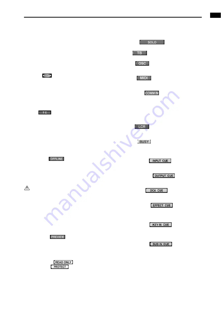
Indicators
One of the following indicators will be displayed
according to the state of the CS1D.
•
EDIT
This indicator will appear if a parameter included in
a scene, patch, unit, or name setting has been edited
after recalling a scene memory. This indicator will
disappear when you save the current settings into a
scene memory or recall a new scene from a scene
memory. This indicator may not disappear in certain
cases, such as when Recall Safe is in effect.
•
TC
This will light if the TC EVENT screen parameter
EVENT RECALLING is set to ENABLE TC. While
this symbol is lit, it is not possible to rewrite the con-
tents of the SCENE or UNIT/PATCH/NAME librar-
ies. This means that functions such as STORE,
STORE UNDO, LINK ON/OFF, TITLE EDIT, SORT,
and LOAD will be unavailable. Before performing
these functions, you must set EVENT RECALLING
to DISABLE.
•
OFFLINE
This symbol will be displayed only in PM1D Man-
ager for Windows software running on your com-
puter. (It will not appear in the display of the CS1D.)
This symbol displayed on your computer indicates
that your computer and the CS1D are offline.
If you are unable to switch to online mode, check
the following points.
1)Have the connections between RS-232-C connec-
tors been made correctly?
2)Are you using an RS-232-C cross cable?
3)Is the power of the CS1D turned on?
4)Has the PM1D editing software been installed
appropriately?
5)Is the RS232C connector of your computer disabled?
•
PREVIEW
This indicator will appear when the PM1D system is
in PREVIEW mode.
In this mode you can view, edit, and save scene set-
tings stored in memory.
•
READ ONLY
PROTECT
The READ ONLY symbol will be displayed if the
scene currently selected for store/recall (shown by
the scene number in the upper right of the display) is
read-only (numbers 00.0–00.9), and the PROTECT
symbol will be displayed if the scene is protected.
6
Operation indicators
The following indicators will appear according to the
operating state of the CS1D.
•
SOLO
This indicator will appear when Solo mode is on.
•
TB
This indicator will appear when Talkback is on.
•
OSC
This indicator will appear when the internal oscilla-
tor is on.
•
MIDI
This indicator will appear when a valid MIDI mes-
sage is received.
•
COMM IN
A red COMM IN symbol will be displayed if a signal
is being input to COMM IN and the COMM IN
DIMMER for MONITOR A is operating.
While this symbol is displayed, you can attenuate the
monitor signal level by using the DIMMER knob in
the MONITOR A screen of the MON/CUE function.
•
LCR
This indicator will light when one or more channels
is set to LCR mode.
•
BUSY
The BUSY symbol will be displayed if data is being
written to the internal memory or the card inserted
in the card slot.
•
INPUT CUE
This symbol will be displayed if the [CUE] switch of
an input channel is on.
•
OUTPUT CUE
This symbol will be displayed if the [CUE] switch of
an output channel is on.
•
DCA CUE
This symbol will be displayed appear if the [CUE]
switch of a DCA group is on.
•
EFFECT CUE
This symbol will be displayed if a CUE button is on
in the EFFECT function EFFECT 1–EFFECT 8
screens or the EFFECT ASSIGN screen.
•
KEY IN CUE
This symbol will be displayed if a KEY IN CUE but-
ton is on in the IN GATE/COMP function GATE
PRM screen.
•
SUB IN CUE
This symbol will be displayed if the KEY IN CUE
button is on in the IN GATE/COMP function GATE
PRM screen.
Summary of Contents for CS1D
Page 1: ...Owner s Manual ...
Page 5: ...Operating Manual ...
Page 6: ...Operating Manual Start up ...
Page 55: ...Operating Manual Basic Operation ...
Page 214: ...Reference Manual ...
Page 215: ...Reference Manual Hardware ...
Page 332: ...Reference Manual Software ...
Page 530: ...Reference Manual Appendices ...


