CS1D Reference Manual (Hardware)
74
[Procedure]
Using DCA faders to control DCA groups 1–12
1. Press any one of the DCA GROUP block DCA
[ASSIGN DCA] switches to select the DCA group
that will be the assign destination.
The [DCA] LEDs of all channels assigned to the cur-
rently selected DCA group will blink.
2. In the INPUT block, ST IN block, or MIX OUTPUT
block, press the [DCA] switches of the channels
that you wish to assign to the above-selected DCA
group.
For the selected channel(s), the [DCA] LED of the
selected assign destination DCA group will light.
You can assign either input channels (input channels,
ST IN channels) or output channels (MIX channels).
Input channels can use DCA groups 1–12, and out-
put channels can use DCA groups 9–12.
It is not possible to assign an output channel to a
DCA group 1–8.
3. Repeat steps 1 and 2 to assign input channels/out-
put channels to other DCA groups.
You can assign multiple channels to a single DCA
group, or assign a single channel to multiple DCA
groups.
•
It is not possible to assign both input channels and
output channels to the same DCA group 9–12. If an
input channel is already assigned, attempting to
assign an output channel will cause a message to be
displayed, and the assignment will not be permitted.
(The same is true of the opposite situation.)
•
When a scene is recalled, the DCA group data of
recall safe channels may be adjusted so that recall safe
settings are consistent within DCA groups 9–12.
Also when a channel library is recalled, the data
recalled to a channel may be adjusted so that settings
are consistent within DCA groups 9–12.
Hint
Input channels/output channels can also be assigned
to DCA groups in the display (IN DCA/MUTE func-
tion DCA ASSIGN screen, or OUT DCA/MUTE
function DCA ASSIGN screen).
4. When you have finished making assignments, press
the [ASSIGN DCA] switches whose LED is lit, to
turn off the LEDs of all [ASSIGN DCA] switches.
Then turn on the FADER STATUS [DCA] switch in
the FADER STATUS section.
The selected LED will light, and you will be able to
use DCA faders 1–12 to control the level of the corre-
sponding DCA group.
5. Operate DCA faders 1–12.
The level of the input channels or output channels
assigned to the corresponding DCA group will
change.
6. If you wish to mute a specific group, press the DCA
[MUTE] switch.
The DCA [MUTE] switch LED will light, and the
input channels/output channels included in that
DCA group will be set to the same status as when the
DCA fader is used to lower the level to the minimum
value (–
∞
dB).
7. When you press the switch once again, the DCA
[MUTE] LED will go dark, and muting will be
defeated.
[Procedure]
Using the DCA faders to control the graphic EQ
Separately from the parametric EQ provided on each
channel, the PM1D system provides twenty-four 31-
band graphic EQ modules which can be inserted into the
desired input channel, MIX channel, MATRIX channel,
or STEREO A/B channel.
By assigning the desired graphic EQ module to the DCA
faders, you can use the DCA faders to control the
amount of boost/cut for each band in realtime.
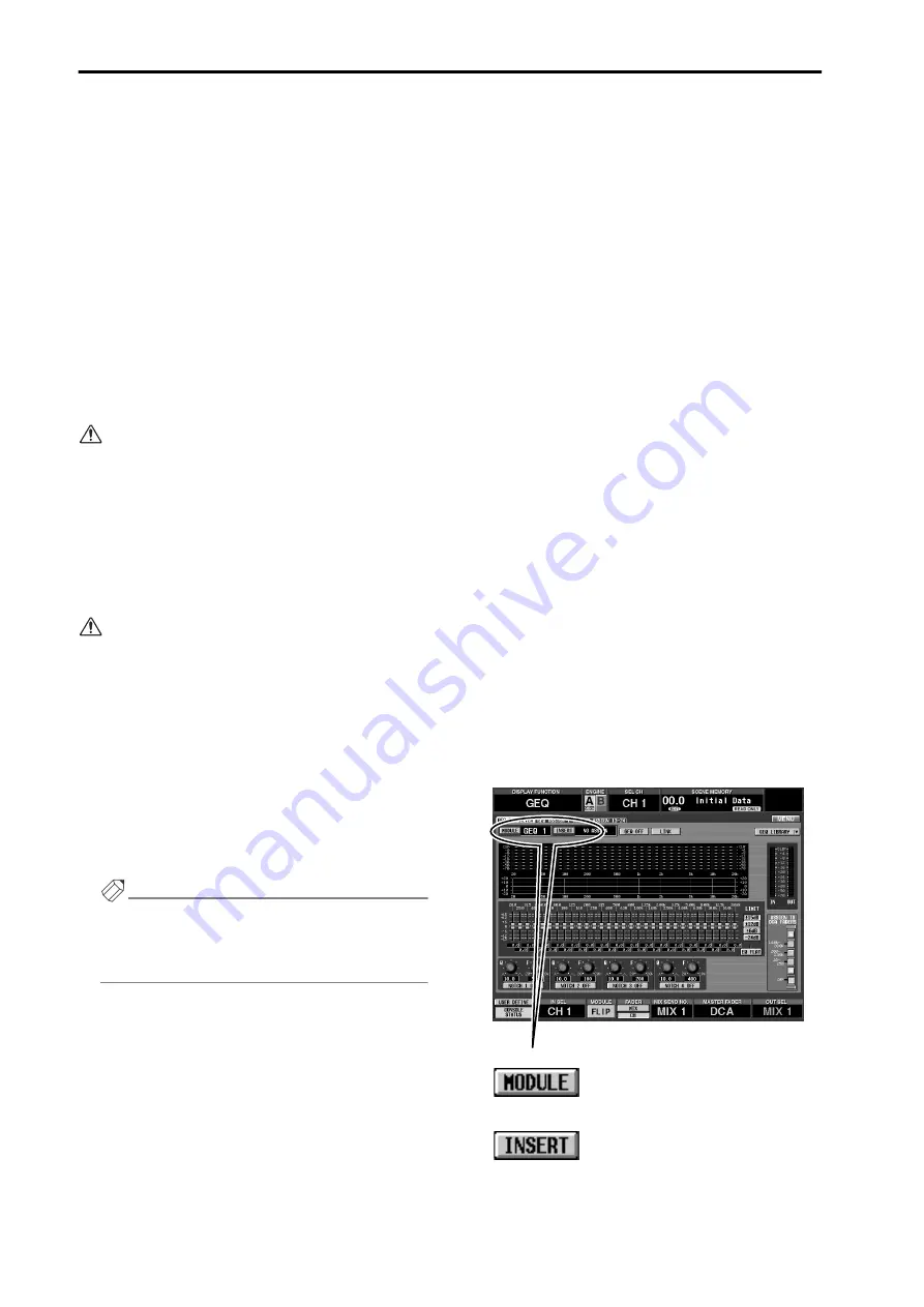
1. In the display, access the GEQ function GEQ
PARAMETER screen.
The GEQ PARAMETER screen can be accessed in the
following ways.
•
From the top panel
In the LCD FUNCTION ACCESS section (MASTER
block), press the [GEQ] switch repeatedly until the
following screen appears.
•
In the display
Click the MENU button
→
GEQ button
→
GEQ
PARAMETER tab.
•
GEQ PARAMETER screen
MODULE button:
INSERT button:
Summary of Contents for CS1D
Page 1: ...Owner s Manual ...
Page 5: ...Operating Manual ...
Page 6: ...Operating Manual Start up ...
Page 55: ...Operating Manual Basic Operation ...
Page 214: ...Reference Manual ...
Page 215: ...Reference Manual Hardware ...
Page 332: ...Reference Manual Software ...
Page 530: ...Reference Manual Appendices ...


