8-49
ELECTRICAL COMPONENTS
WARNING
Never use a fuse with an amperage rating
other than that specified. Improvising or
using a fuse with the wrong amperage rat-
ing may cause extensive damage to the
electrical system, cause the lighting and
ignition systems to malfunction and could
possibly cause a fire.
▼▼▼▼▼▼▼▼▼▼▼▼▼▼▼▼▼▼▼▼▼▼▼▼▼▼▼▼▼▼▼▼
4. Install:
• Seat
EAS28030
CHECKING AND CHARGING THE BATTERY
EWA13290
WARNING
Batteries generate explosive hydrogen gas
and contain electrolyte which is made of
poisonousand highly caustic sulfuric acid.
Therefore, always follow these preventive
measures:
•
Wear protective eye gear when handling or
working near batteries.
•
Charge batteries in a well-ventilated area.
•
Keep batteries away from fire, sparks or
open flames (e.g., welding equipment,
lighted cigarettes).
•
DO NOT SMOKE when charging or han-
dling batteries.
•
KEEP BATTERIES AND ELECTROLYTE
OUT OF REACH OF CHILDREN.
•
Avoid bodily contact with electrolyte as it
can cause severe burns or permanent eye
injury.
FIRST AID IN CASE OF BODILY CONTACT:
EXTERNAL
•
Skin — Wash with water.
•
Eyes — Flush with water for 15 minutes
and get immediate medical attention.
INTERNAL
•
Drink large quantities of water or milk fol-
lowed with milk of magnesia, beaten egg
or vegetable oil. Get immediate medical
attention.
ECA13660
CAUTION:
•
This is a sealed battery. Never remove the
sealing caps because the balance be-
tween cells will not be maintained and bat-
tery performance will deteriorate.
•
Charging time, charging amperage and
charging voltage for an MF battery are dif-
ferent from those of conventional batter-
ies. The MF battery should be charged as
explained in the charging method illustra-
tions. If the battery is overcharged, the
electrolyte level will drop considerably.
Therefore, take special care when charg-
ing the battery.
NOTE:
Since MF batteries are sealed, it is not possible
to check the charge state of the battery by
measuring the specific gravity of the elec-
trolyte.
Therefore, the charge of the battery has to be
checked by measuring the voltage at the bat-
tery terminals.
1. Remove:
• Seat
• Battery stay
2. Disconnect:
• Battery leads (from the battery terminals)
ECA13640
CAUTION:
First, disconnect the negative battery lead
“1”, and then positive battery lead “2”.
Summary of Contents for 2008 Tenere
Page 1: ...SERVICE MANUAL 2008 11D F8197 E0 XT660Z ...
Page 8: ......
Page 24: ......
Page 44: ...2 20 TIGHTENING TORQUES Cylinder head tightening sequence 2 4 3 1 ...
Page 54: ...2 30 COOLING SYSTEM DIAGRAMS 1 2 3 4 5 6 7 9 10 11 12 5 8 11 A ...
Page 57: ...2 33 LUBRICATION DIAGRAMS LUBRICATION DIAGRAMS 1 A A A A B B B A A B 3 2 2 4 1 1 5 5 ...
Page 59: ...2 35 LUBRICATION DIAGRAMS A A A A 3 1 2 3 4 ...
Page 60: ...2 36 LUBRICATION DIAGRAMS 1 Oil delivery pipe 2 2 Oil delivery pipe 1 3 Oil filter 4 Oil pump ...
Page 61: ...2 37 LUBRICATION DIAGRAMS 1 7 2 3 4 5 6 A ...
Page 63: ...2 39 LUBRICATION DIAGRAMS 1 6 5 4 3 2 ...
Page 65: ...2 41 CABLE ROUTING CABLE ROUTING ...
Page 67: ...2 43 CABLE ROUTING ...
Page 69: ...2 45 CABLE ROUTING ...
Page 71: ...2 47 CABLE ROUTING ...
Page 73: ...2 49 CABLE ROUTING ...
Page 75: ...2 51 CABLE ROUTING ...
Page 77: ...2 53 CABLE ROUTING ...
Page 79: ...2 55 CABLE ROUTING ...
Page 81: ...2 57 CABLE ROUTING ...
Page 83: ...2 59 CABLE ROUTING ...
Page 176: ...4 56 FRONT FORK WARNING Make sure the brake hoses are routed prop erly 1 2 3 ...
Page 270: ......
Page 284: ......
Page 301: ...7 17 FUEL INJECTION SYSTEM WIRING DIAGRAM ...
Page 324: ......
Page 327: ...8 1 IGNITION SYSTEM EAS27090 IGNITION SYSTEM EAS27110 CIRCUIT DIAGRAM ...
Page 331: ...8 5 ELECTRIC STARTING SYSTEM EAS27160 ELECTRIC STARTING SYSTEM EAS27170 CIRCUIT DIAGRAM ...
Page 337: ...8 11 CHARGING SYSTEM EAS27200 CHARGING SYSTEM EAS27210 CIRCUIT DIAGRAM ...
Page 338: ...8 12 CHARGING SYSTEM 2 A C magneto 5 Rectifier regulator 7 Battery 8 Main fuse ...
Page 340: ...8 14 CHARGING SYSTEM ...
Page 341: ...8 15 LIGHTING SYSTEM EAS27240 LIGHTING SYSTEM EAS27250 CIRCUIT DIAGRAM ...
Page 345: ...8 19 SIGNALING SYSTEM EAS27270 SIGNALING SYSTEM EAS27280 CIRCUIT DIAGRAM ...
Page 351: ...8 25 COOLING SYSTEM EAS00807 COOLING SYSTEM CIRCUIT DIAGRAM ...
Page 354: ...8 28 COOLING SYSTEM ...
Page 355: ...8 29 IMMOBILIZER SYSTEM ET5YU1002 IMMOBILIZER SYSTEM ET5YU1003 CIRCUIT DIAGRAM ...
Page 364: ...8 38 IMMOBILIZER SYSTEM ...
Page 365: ...8 39 ELECTRICAL COMPONENTS EAS27970 ELECTRICAL COMPONENTS ...
Page 367: ...8 41 ELECTRICAL COMPONENTS ...
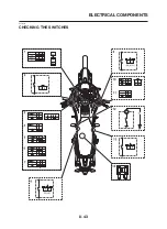
Page 369: ...8 43 ELECTRICAL COMPONENTS EAS27980 CHECKING THE SWITCHES ...
Page 388: ......
Page 390: ......
Page 396: ...COLOR CODE ...
Page 397: ......
Page 398: ...YAMAHA MOTOR ITALIA S P A ...
Page 399: ...XT660Z 2008 WIRING DIAGRAM ...


