


8-33
IMMOBILIZER SYSTEM
Standby mode
a. Main switch “ON”
b. Main switch “OFF”
c. LED on
d. LED off
e. Standby mode on
f. Standby mode off
Standard key registration:
Standard key registration is required when a standard key is lost and needs to be replaced, or when
the code re-registering key is re-registered after the immobilizer unit or ECU are replaced.
NOTE:
Do not start the engine with a standard key that has not been registered. If the main switch is turned
“ON” with a standard key that has not been registered, the immobilizer system indicator light flash-
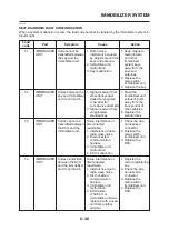
es to indicate fault code “52”. (Refer to “SELF-DIAGNOSIS FAULT CODE INDICATION” on page
8-36).
1. Check that the immobilizer system indicator light signals the standby mode.
2. Using the code re-registering key, turn the main switch to “ON”, then “OFF”, and then remove the
key within 5 seconds.
3. Insert the first standard key to be registered into the main switch, then turn the key to “ON”
within 5 seconds to activate the key registration mode.
NOTE:
The existing standard key code is erased from the memory when the key registration mode is acti-
vated. When the key registration mode is activated, the immobilizer system indicator light flashes
rapidly.
4. While the indicator light is flashing, turn the main switch to “OFF”, remove the key, and within 5
seconds, insert the second standard key to be registered into the main switch.
NOTE:
If the immobilizer system indicator light stops flashing 5 seconds after the first standard key is reg-
istered, the registration mode is deactivated. If this occurs, the second standard key cannot be reg-
istered, and steps 2 to 4 need to be repeated to register both standard keys.
5. Turn the main switch to “ON”.
NOTE:
When the indicator light goes off, the registration is complete.
6. Check that the engine can be started with the two registered standard keys.
Summary of Contents for 2008 Tenere
Page 1: ...SERVICE MANUAL 2008 11D F8197 E0 XT660Z ...
Page 8: ......
Page 24: ......
Page 44: ...2 20 TIGHTENING TORQUES Cylinder head tightening sequence 2 4 3 1 ...
Page 54: ...2 30 COOLING SYSTEM DIAGRAMS 1 2 3 4 5 6 7 9 10 11 12 5 8 11 A ...
Page 57: ...2 33 LUBRICATION DIAGRAMS LUBRICATION DIAGRAMS 1 A A A A B B B A A B 3 2 2 4 1 1 5 5 ...
Page 59: ...2 35 LUBRICATION DIAGRAMS A A A A 3 1 2 3 4 ...
Page 60: ...2 36 LUBRICATION DIAGRAMS 1 Oil delivery pipe 2 2 Oil delivery pipe 1 3 Oil filter 4 Oil pump ...
Page 61: ...2 37 LUBRICATION DIAGRAMS 1 7 2 3 4 5 6 A ...
Page 63: ...2 39 LUBRICATION DIAGRAMS 1 6 5 4 3 2 ...
Page 65: ...2 41 CABLE ROUTING CABLE ROUTING ...
Page 67: ...2 43 CABLE ROUTING ...
Page 69: ...2 45 CABLE ROUTING ...
Page 71: ...2 47 CABLE ROUTING ...
Page 73: ...2 49 CABLE ROUTING ...
Page 75: ...2 51 CABLE ROUTING ...
Page 77: ...2 53 CABLE ROUTING ...
Page 79: ...2 55 CABLE ROUTING ...
Page 81: ...2 57 CABLE ROUTING ...
Page 83: ...2 59 CABLE ROUTING ...
Page 176: ...4 56 FRONT FORK WARNING Make sure the brake hoses are routed prop erly 1 2 3 ...
Page 270: ......
Page 284: ......
Page 301: ...7 17 FUEL INJECTION SYSTEM WIRING DIAGRAM ...
Page 324: ......
Page 327: ...8 1 IGNITION SYSTEM EAS27090 IGNITION SYSTEM EAS27110 CIRCUIT DIAGRAM ...
Page 331: ...8 5 ELECTRIC STARTING SYSTEM EAS27160 ELECTRIC STARTING SYSTEM EAS27170 CIRCUIT DIAGRAM ...
Page 337: ...8 11 CHARGING SYSTEM EAS27200 CHARGING SYSTEM EAS27210 CIRCUIT DIAGRAM ...
Page 338: ...8 12 CHARGING SYSTEM 2 A C magneto 5 Rectifier regulator 7 Battery 8 Main fuse ...
Page 340: ...8 14 CHARGING SYSTEM ...
Page 341: ...8 15 LIGHTING SYSTEM EAS27240 LIGHTING SYSTEM EAS27250 CIRCUIT DIAGRAM ...
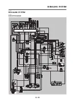
Page 345: ...8 19 SIGNALING SYSTEM EAS27270 SIGNALING SYSTEM EAS27280 CIRCUIT DIAGRAM ...
Page 351: ...8 25 COOLING SYSTEM EAS00807 COOLING SYSTEM CIRCUIT DIAGRAM ...
Page 354: ...8 28 COOLING SYSTEM ...
Page 355: ...8 29 IMMOBILIZER SYSTEM ET5YU1002 IMMOBILIZER SYSTEM ET5YU1003 CIRCUIT DIAGRAM ...
Page 364: ...8 38 IMMOBILIZER SYSTEM ...
Page 365: ...8 39 ELECTRICAL COMPONENTS EAS27970 ELECTRICAL COMPONENTS ...
Page 367: ...8 41 ELECTRICAL COMPONENTS ...
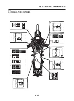
Page 369: ...8 43 ELECTRICAL COMPONENTS EAS27980 CHECKING THE SWITCHES ...
Page 388: ......
Page 390: ......
Page 396: ...COLOR CODE ...
Page 397: ......
Page 398: ...YAMAHA MOTOR ITALIA S P A ...
Page 399: ...XT660Z 2008 WIRING DIAGRAM ...