4-54
FRONT FORK
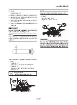
5. Install:
• Oil seal “1”
(with the fork seal driver weight and fork seal
driver attachment)
CAUTION:
Make sure the numbered side of the oil seal
faces up.
NOTE:
• Before installing the oil seal, lubricate its lips
with lithium-soap-based grease.
• Lubricate the outer surface of the inner tube
with fork oil.
• Before installing the oil seal, cover the top of
the front fork leg with a plastic bag “2” to pro-
tect the oil seal during installation.
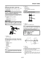
6. Install:
• Oil seal clip “1”
1
Fork seal driver weight
90890-01367
NOTE:
Adjust the oil seal clip so that it fits into the out-
er tube’s groove.
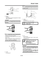
7. Install:
• Dust seal “1”
(with the fork seal driver weight)
Quantity (each front fork leg)
650.0 cm
3
(21.97 US oz)
(22.87 Imp.oz)
Recommended oil
Fork oil 10W or equivalent
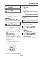
8. Fill:
• Front fork leg
(with the specified amount of the recom-
mended fork oil)
1
CAUTION:
•
Be sure to use the recommended fork oil.
Other oils may have an adverse effect on
front fork performance.
•
When disassembling and assembling the
front fork leg, do not allow any foreign ma-
terial to enter the front fork.
Summary of Contents for 2008 Tenere
Page 1: ...SERVICE MANUAL 2008 11D F8197 E0 XT660Z ...
Page 8: ......
Page 24: ......
Page 44: ...2 20 TIGHTENING TORQUES Cylinder head tightening sequence 2 4 3 1 ...
Page 54: ...2 30 COOLING SYSTEM DIAGRAMS 1 2 3 4 5 6 7 9 10 11 12 5 8 11 A ...
Page 57: ...2 33 LUBRICATION DIAGRAMS LUBRICATION DIAGRAMS 1 A A A A B B B A A B 3 2 2 4 1 1 5 5 ...
Page 59: ...2 35 LUBRICATION DIAGRAMS A A A A 3 1 2 3 4 ...
Page 60: ...2 36 LUBRICATION DIAGRAMS 1 Oil delivery pipe 2 2 Oil delivery pipe 1 3 Oil filter 4 Oil pump ...
Page 61: ...2 37 LUBRICATION DIAGRAMS 1 7 2 3 4 5 6 A ...
Page 63: ...2 39 LUBRICATION DIAGRAMS 1 6 5 4 3 2 ...
Page 65: ...2 41 CABLE ROUTING CABLE ROUTING ...
Page 67: ...2 43 CABLE ROUTING ...
Page 69: ...2 45 CABLE ROUTING ...
Page 71: ...2 47 CABLE ROUTING ...
Page 73: ...2 49 CABLE ROUTING ...
Page 75: ...2 51 CABLE ROUTING ...
Page 77: ...2 53 CABLE ROUTING ...
Page 79: ...2 55 CABLE ROUTING ...
Page 81: ...2 57 CABLE ROUTING ...
Page 83: ...2 59 CABLE ROUTING ...
Page 176: ...4 56 FRONT FORK WARNING Make sure the brake hoses are routed prop erly 1 2 3 ...
Page 270: ......
Page 284: ......
Page 301: ...7 17 FUEL INJECTION SYSTEM WIRING DIAGRAM ...
Page 324: ......
Page 327: ...8 1 IGNITION SYSTEM EAS27090 IGNITION SYSTEM EAS27110 CIRCUIT DIAGRAM ...
Page 331: ...8 5 ELECTRIC STARTING SYSTEM EAS27160 ELECTRIC STARTING SYSTEM EAS27170 CIRCUIT DIAGRAM ...
Page 337: ...8 11 CHARGING SYSTEM EAS27200 CHARGING SYSTEM EAS27210 CIRCUIT DIAGRAM ...
Page 338: ...8 12 CHARGING SYSTEM 2 A C magneto 5 Rectifier regulator 7 Battery 8 Main fuse ...
Page 340: ...8 14 CHARGING SYSTEM ...
Page 341: ...8 15 LIGHTING SYSTEM EAS27240 LIGHTING SYSTEM EAS27250 CIRCUIT DIAGRAM ...
Page 345: ...8 19 SIGNALING SYSTEM EAS27270 SIGNALING SYSTEM EAS27280 CIRCUIT DIAGRAM ...
Page 351: ...8 25 COOLING SYSTEM EAS00807 COOLING SYSTEM CIRCUIT DIAGRAM ...
Page 354: ...8 28 COOLING SYSTEM ...
Page 355: ...8 29 IMMOBILIZER SYSTEM ET5YU1002 IMMOBILIZER SYSTEM ET5YU1003 CIRCUIT DIAGRAM ...
Page 364: ...8 38 IMMOBILIZER SYSTEM ...
Page 365: ...8 39 ELECTRICAL COMPONENTS EAS27970 ELECTRICAL COMPONENTS ...
Page 367: ...8 41 ELECTRICAL COMPONENTS ...
Page 369: ...8 43 ELECTRICAL COMPONENTS EAS27980 CHECKING THE SWITCHES ...
Page 388: ......
Page 390: ......
Page 396: ...COLOR CODE ...
Page 397: ......
Page 398: ...YAMAHA MOTOR ITALIA S P A ...
Page 399: ...XT660Z 2008 WIRING DIAGRAM ...


