4-41
REAR BRAKE
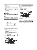
NOTE:
To collect any remaining brake fluid, place a
container under the master cylinder and the
end of the brake hose.
2. Remove:
• Cotter pin
• Washer
• Pin “4”
• Brake master cylinder mounting screw “5”
EAS22720
CHECKING THE REAR BRAKE MASTER
CYLINDER
1. Check:
• Brake master cylinder
Damage/scratches/wear
→
Replace.
• Brake fluid delivery passages
(brake master cylinder body)
Obstruction
→
Blow out with compressed air.
2. Check:
• Brake master cylinder kit
• Damage/scratches/wear
→
Replace.
3. Check:
• Brake fluid reservoir
Cracks/damage
→
Replace.
• Brake fluid reservoir diaphragm
Cracks/damage
→
Replace.
4. Check:
• Brake hoses
Cracks/damage/wear
→
Replace.
EAS22730
ASSEMBLING THE REAR BRAKE MASTER
CYLINDER
EWA13520
WARNING
•
Before installation, all internal brake com-
ponents should be cleaned and lubricated
with clean or new brake fluid.
•
Never use solvents on internal brake com-
ponents.
•
Whenever a master cylinder is disassem-
bled, replace the piston seals and dust seals.
Recommended fluid
DOT 4
1. Install:
• Brake master cylinder kit
• Joint “1”
NOTE:
Turn the adjusting bolt “2” until the clearance “a” is
within the specified limits when install the joint “1”.
Clearance “a”
2.1 mm (0.08 in)
2. Tighten:
• Nut “3”
Brake master cylinder adjusting
nut
18 Nm (1.8 m·kg, 13 ft·lb)
EAS22740
INSTALLING THE REAR BRAKE MASTER
CYLINDER
1. Install:
• Brake master cylinder
• Pin “1”
• Washer “2”
• Cotter pin “3”
NOTE:
Install the cotter pin and bend the ends as
shown.
New
Summary of Contents for 2008 Tenere
Page 1: ...SERVICE MANUAL 2008 11D F8197 E0 XT660Z ...
Page 8: ......
Page 24: ......
Page 44: ...2 20 TIGHTENING TORQUES Cylinder head tightening sequence 2 4 3 1 ...
Page 54: ...2 30 COOLING SYSTEM DIAGRAMS 1 2 3 4 5 6 7 9 10 11 12 5 8 11 A ...
Page 57: ...2 33 LUBRICATION DIAGRAMS LUBRICATION DIAGRAMS 1 A A A A B B B A A B 3 2 2 4 1 1 5 5 ...
Page 59: ...2 35 LUBRICATION DIAGRAMS A A A A 3 1 2 3 4 ...
Page 60: ...2 36 LUBRICATION DIAGRAMS 1 Oil delivery pipe 2 2 Oil delivery pipe 1 3 Oil filter 4 Oil pump ...
Page 61: ...2 37 LUBRICATION DIAGRAMS 1 7 2 3 4 5 6 A ...
Page 63: ...2 39 LUBRICATION DIAGRAMS 1 6 5 4 3 2 ...
Page 65: ...2 41 CABLE ROUTING CABLE ROUTING ...
Page 67: ...2 43 CABLE ROUTING ...
Page 69: ...2 45 CABLE ROUTING ...
Page 71: ...2 47 CABLE ROUTING ...
Page 73: ...2 49 CABLE ROUTING ...
Page 75: ...2 51 CABLE ROUTING ...
Page 77: ...2 53 CABLE ROUTING ...
Page 79: ...2 55 CABLE ROUTING ...
Page 81: ...2 57 CABLE ROUTING ...
Page 83: ...2 59 CABLE ROUTING ...
Page 176: ...4 56 FRONT FORK WARNING Make sure the brake hoses are routed prop erly 1 2 3 ...
Page 270: ......
Page 284: ......
Page 301: ...7 17 FUEL INJECTION SYSTEM WIRING DIAGRAM ...
Page 324: ......
Page 327: ...8 1 IGNITION SYSTEM EAS27090 IGNITION SYSTEM EAS27110 CIRCUIT DIAGRAM ...
Page 331: ...8 5 ELECTRIC STARTING SYSTEM EAS27160 ELECTRIC STARTING SYSTEM EAS27170 CIRCUIT DIAGRAM ...
Page 337: ...8 11 CHARGING SYSTEM EAS27200 CHARGING SYSTEM EAS27210 CIRCUIT DIAGRAM ...
Page 338: ...8 12 CHARGING SYSTEM 2 A C magneto 5 Rectifier regulator 7 Battery 8 Main fuse ...
Page 340: ...8 14 CHARGING SYSTEM ...
Page 341: ...8 15 LIGHTING SYSTEM EAS27240 LIGHTING SYSTEM EAS27250 CIRCUIT DIAGRAM ...
Page 345: ...8 19 SIGNALING SYSTEM EAS27270 SIGNALING SYSTEM EAS27280 CIRCUIT DIAGRAM ...
Page 351: ...8 25 COOLING SYSTEM EAS00807 COOLING SYSTEM CIRCUIT DIAGRAM ...
Page 354: ...8 28 COOLING SYSTEM ...
Page 355: ...8 29 IMMOBILIZER SYSTEM ET5YU1002 IMMOBILIZER SYSTEM ET5YU1003 CIRCUIT DIAGRAM ...
Page 364: ...8 38 IMMOBILIZER SYSTEM ...
Page 365: ...8 39 ELECTRICAL COMPONENTS EAS27970 ELECTRICAL COMPONENTS ...
Page 367: ...8 41 ELECTRICAL COMPONENTS ...
Page 369: ...8 43 ELECTRICAL COMPONENTS EAS27980 CHECKING THE SWITCHES ...
Page 388: ......
Page 390: ......
Page 396: ...COLOR CODE ...
Page 397: ......
Page 398: ...YAMAHA MOTOR ITALIA S P A ...
Page 399: ...XT660Z 2008 WIRING DIAGRAM ...


