


4-46
HANDLEBAR
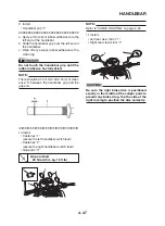
4. Install:
• Front brake master cylinder “1”
• Front brake master cylinder holder “2”
NOTE:
• Make sure that the "UP" mark “a” with the
bracket is pointed upward.
• Align the punch mark “b” on the handlebar
with the gap of the master cylinder bracket.
Front brake master cylinder
holder bolt
7 Nm (0.7 m·kg, 5.1 ft·lb)
5. Connect:
• Front brake switch lead “3”
NOTE:
• Tighten the bolts in stages and maintain an
equal gap on each side of the bracket to spec-
ification.
• Check the brake lever for smooth action.
WARNING
Proper cable routing is essential to assure
safe motorcycle operation. Refer to “CABLE
ROUTING” on page 2-42.
6. Install:
• Left handlebar switch “1”
NOTE:
Align the projection “a” on the left handlebar
switch with the hole in the handlebar.
Handlebar switch bolt
1.5 Nm (0.15 m·kg, 1.05 ft·lb)
WARNING
Proper cable routing is essential to assure
safe motorcycle operation. Refer to “CABLE
ROUTING” on page 2-42.
7. Install:
• Clutch cable “1”
• Cable boot “2”
NOTE:
• Lubricate the pivoting part “a” of the clutch
lever.
• Turn in the adjuster “b” on the lever holder un-
til tight. Next, align the slit in the adjuster and
cable socket with the slit in the lever holder.
• Insert the cable end into the lever hole. Next,
while pulling the outer cable in the direction
opposite to the lever, seat the outer cable into
the cable socket.
8. Connect:
• Clutch lever switch “3”
WARNING
Check the clutch lever for smooth action.
Refer to “CABLE ROUTING” on page 2-42.
Summary of Contents for 2008 Tenere
Page 1: ...SERVICE MANUAL 2008 11D F8197 E0 XT660Z ...
Page 8: ......
Page 24: ......
Page 44: ...2 20 TIGHTENING TORQUES Cylinder head tightening sequence 2 4 3 1 ...
Page 54: ...2 30 COOLING SYSTEM DIAGRAMS 1 2 3 4 5 6 7 9 10 11 12 5 8 11 A ...
Page 57: ...2 33 LUBRICATION DIAGRAMS LUBRICATION DIAGRAMS 1 A A A A B B B A A B 3 2 2 4 1 1 5 5 ...
Page 59: ...2 35 LUBRICATION DIAGRAMS A A A A 3 1 2 3 4 ...
Page 60: ...2 36 LUBRICATION DIAGRAMS 1 Oil delivery pipe 2 2 Oil delivery pipe 1 3 Oil filter 4 Oil pump ...
Page 61: ...2 37 LUBRICATION DIAGRAMS 1 7 2 3 4 5 6 A ...
Page 63: ...2 39 LUBRICATION DIAGRAMS 1 6 5 4 3 2 ...
Page 65: ...2 41 CABLE ROUTING CABLE ROUTING ...
Page 67: ...2 43 CABLE ROUTING ...
Page 69: ...2 45 CABLE ROUTING ...
Page 71: ...2 47 CABLE ROUTING ...
Page 73: ...2 49 CABLE ROUTING ...
Page 75: ...2 51 CABLE ROUTING ...
Page 77: ...2 53 CABLE ROUTING ...
Page 79: ...2 55 CABLE ROUTING ...
Page 81: ...2 57 CABLE ROUTING ...
Page 83: ...2 59 CABLE ROUTING ...
Page 176: ...4 56 FRONT FORK WARNING Make sure the brake hoses are routed prop erly 1 2 3 ...
Page 270: ......
Page 284: ......
Page 301: ...7 17 FUEL INJECTION SYSTEM WIRING DIAGRAM ...
Page 324: ......
Page 327: ...8 1 IGNITION SYSTEM EAS27090 IGNITION SYSTEM EAS27110 CIRCUIT DIAGRAM ...
Page 331: ...8 5 ELECTRIC STARTING SYSTEM EAS27160 ELECTRIC STARTING SYSTEM EAS27170 CIRCUIT DIAGRAM ...
Page 337: ...8 11 CHARGING SYSTEM EAS27200 CHARGING SYSTEM EAS27210 CIRCUIT DIAGRAM ...
Page 338: ...8 12 CHARGING SYSTEM 2 A C magneto 5 Rectifier regulator 7 Battery 8 Main fuse ...
Page 340: ...8 14 CHARGING SYSTEM ...
Page 341: ...8 15 LIGHTING SYSTEM EAS27240 LIGHTING SYSTEM EAS27250 CIRCUIT DIAGRAM ...
Page 345: ...8 19 SIGNALING SYSTEM EAS27270 SIGNALING SYSTEM EAS27280 CIRCUIT DIAGRAM ...
Page 351: ...8 25 COOLING SYSTEM EAS00807 COOLING SYSTEM CIRCUIT DIAGRAM ...
Page 354: ...8 28 COOLING SYSTEM ...
Page 355: ...8 29 IMMOBILIZER SYSTEM ET5YU1002 IMMOBILIZER SYSTEM ET5YU1003 CIRCUIT DIAGRAM ...
Page 364: ...8 38 IMMOBILIZER SYSTEM ...
Page 365: ...8 39 ELECTRICAL COMPONENTS EAS27970 ELECTRICAL COMPONENTS ...
Page 367: ...8 41 ELECTRICAL COMPONENTS ...
Page 369: ...8 43 ELECTRICAL COMPONENTS EAS27980 CHECKING THE SWITCHES ...
Page 388: ......
Page 390: ......
Page 396: ...COLOR CODE ...
Page 397: ......
Page 398: ...YAMAHA MOTOR ITALIA S P A ...
Page 399: ...XT660Z 2008 WIRING DIAGRAM ...