


7-32
FUEL INJECTION SYSTEM
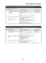
Fault code No.
16
Symptom
The throttle position sensor is detected stuck.
Used diagnostic code No. 01 (throttle position sensor)
Order
Item/components
Check or maintenance job
Restore method
1
Defective throttle position sensor
Replace the sensor if it is defective.
Refer to “THROTTLE BODY ASSEMBLY”.
Reinstated by start-
ing the engine, oper-
ating it at idle, and
then racing it.
2
Throttle position sensor installation
Execute the diagnostic mode. (Code No. 01)
Check the sensor for looseness or pinching.
Check that the sensor is installed in the specified
position. Refer to “THROTTLE BODY ASSEM-
BLY” in chapter 7.
Fault code No.
19
Symptom
Open circuit is detected in the input wire from the sidestand switch to the ECU.
Used diagnostic code No. 20 (sidestand switch)
Order
Item/components
Check or maintenance job
Restore method
1
Coupler connections
ECU coupler
Blue/Black connector
Check the couplers for any pins that may have
pulled out.
Check that the couplers are securely locked.
If necessary, repair the coupler or securely con-
nect it.
If the transmission is
in gear, it is rein-
stated by retracting
the sidestand.
If the transmission is
in neutral, it is rein-
stated by reconnect-
ing the wiring.
2
Open or short circuit in the wire har-
ness
Repair or replace if there is an open or short cir-
cuit between the ECU and sidestand switch.
Blue/Black
3
Defective sidestand switch
Execute the diagnostic mode. (Code No. 20)
Replace the switch if it is defective.
Refer to “CHECKING THE SWITCHES”
on page 8-43.
Fault code No.
21
Symptom
Open or short circuit is detected from the coolant temperature sensor.
Used diagnostic code No. 06 (coolant temperature sensor)
Order
Item/components
Check or maintenance job
Restore method
1
Coolant temperature sensor instal-
lation
Check the sensor for looseness or pinching.
Reinstated by set-
ting the main switch
to “ON’.
2
Coupler connections
Coolant temperature sensor cou-
pler
ECU coupler
Check the coupler for any pins that may have
pulled out.
Check that the couplers are securely locked.
If necessary, repair the coupler or securely con-
nect it.
3
Open or short circuit in the wire har-
ness
Repair or replace if there is an open or short cir-
cuit between the wire harnesses.
Black/Blue - Black/Blue
Green/Red - Green/Red
4
Defective coolant temperature sen-
sor
Execute the diagnostic mode. (Code No. 06)
Replace the sensor if it is defective.
Refer to “COOLING SYSTEM” on page 8-25.
Summary of Contents for 2008 Tenere
Page 1: ...SERVICE MANUAL 2008 11D F8197 E0 XT660Z ...
Page 8: ......
Page 24: ......
Page 44: ...2 20 TIGHTENING TORQUES Cylinder head tightening sequence 2 4 3 1 ...
Page 54: ...2 30 COOLING SYSTEM DIAGRAMS 1 2 3 4 5 6 7 9 10 11 12 5 8 11 A ...
Page 57: ...2 33 LUBRICATION DIAGRAMS LUBRICATION DIAGRAMS 1 A A A A B B B A A B 3 2 2 4 1 1 5 5 ...
Page 59: ...2 35 LUBRICATION DIAGRAMS A A A A 3 1 2 3 4 ...
Page 60: ...2 36 LUBRICATION DIAGRAMS 1 Oil delivery pipe 2 2 Oil delivery pipe 1 3 Oil filter 4 Oil pump ...
Page 61: ...2 37 LUBRICATION DIAGRAMS 1 7 2 3 4 5 6 A ...
Page 63: ...2 39 LUBRICATION DIAGRAMS 1 6 5 4 3 2 ...
Page 65: ...2 41 CABLE ROUTING CABLE ROUTING ...
Page 67: ...2 43 CABLE ROUTING ...
Page 69: ...2 45 CABLE ROUTING ...
Page 71: ...2 47 CABLE ROUTING ...
Page 73: ...2 49 CABLE ROUTING ...
Page 75: ...2 51 CABLE ROUTING ...
Page 77: ...2 53 CABLE ROUTING ...
Page 79: ...2 55 CABLE ROUTING ...
Page 81: ...2 57 CABLE ROUTING ...
Page 83: ...2 59 CABLE ROUTING ...
Page 176: ...4 56 FRONT FORK WARNING Make sure the brake hoses are routed prop erly 1 2 3 ...
Page 270: ......
Page 284: ......
Page 301: ...7 17 FUEL INJECTION SYSTEM WIRING DIAGRAM ...
Page 324: ......
Page 327: ...8 1 IGNITION SYSTEM EAS27090 IGNITION SYSTEM EAS27110 CIRCUIT DIAGRAM ...
Page 331: ...8 5 ELECTRIC STARTING SYSTEM EAS27160 ELECTRIC STARTING SYSTEM EAS27170 CIRCUIT DIAGRAM ...
Page 337: ...8 11 CHARGING SYSTEM EAS27200 CHARGING SYSTEM EAS27210 CIRCUIT DIAGRAM ...
Page 338: ...8 12 CHARGING SYSTEM 2 A C magneto 5 Rectifier regulator 7 Battery 8 Main fuse ...
Page 340: ...8 14 CHARGING SYSTEM ...
Page 341: ...8 15 LIGHTING SYSTEM EAS27240 LIGHTING SYSTEM EAS27250 CIRCUIT DIAGRAM ...
Page 345: ...8 19 SIGNALING SYSTEM EAS27270 SIGNALING SYSTEM EAS27280 CIRCUIT DIAGRAM ...
Page 351: ...8 25 COOLING SYSTEM EAS00807 COOLING SYSTEM CIRCUIT DIAGRAM ...
Page 354: ...8 28 COOLING SYSTEM ...
Page 355: ...8 29 IMMOBILIZER SYSTEM ET5YU1002 IMMOBILIZER SYSTEM ET5YU1003 CIRCUIT DIAGRAM ...
Page 364: ...8 38 IMMOBILIZER SYSTEM ...
Page 365: ...8 39 ELECTRICAL COMPONENTS EAS27970 ELECTRICAL COMPONENTS ...
Page 367: ...8 41 ELECTRICAL COMPONENTS ...
Page 369: ...8 43 ELECTRICAL COMPONENTS EAS27980 CHECKING THE SWITCHES ...
Page 388: ......
Page 390: ......
Page 396: ...COLOR CODE ...
Page 397: ......
Page 398: ...YAMAHA MOTOR ITALIA S P A ...
Page 399: ...XT660Z 2008 WIRING DIAGRAM ...