WorkCentre Pro 423/428
2-186
CHAPTER 2 TROUBLESHOOTING
03/02
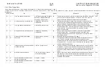
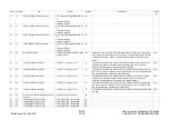
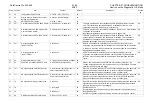
How to use the Diagnostic C/E Mode
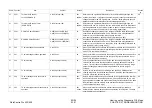
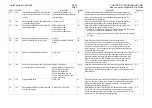
Chain Function
Item
Content
Default
Description
Access
by
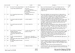
57
34
iFAX(Internet Fax) Function
0:TIFF-S 1:TIFF-F 2:TIFF-J
00
57
35
Priority Order in Received Document
Sorting by Line Services
0:Dial-in 1:Number Display
00
57
36
SMTP Send I/F Activation
0: Stop 1: Start
00
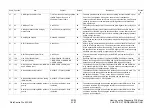
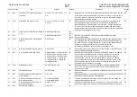
57
50**
Call Restriction on PSTN0 (NCU Guard)
0: Enable call 1: Disable call
00
This data prohibits a G3 fax or telephone call to NCU0 installed on the main
unit. This restriction is applied when NCU0 is installed but the line is not
connected or when NCU0 is used for reception only.
CE
57
51**
Call Restriction on G3CH0 (Channel 0
Communication Guard)
0: Enable call 1: Disable call
00
This data prohibits a G3 fax to NCU0 installed on the main unit. Function=050
Telephone call is enabled.
Individually reflectable on each speed dial (refer to page 2-207)
CE
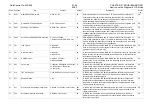
57
52**
Call Restriction on EXT0 (NCU Guard)
0: Enable call 1: Disable call
00
This data prohibits a G3 fax or telephone call to an extension when the
optional NCU0 for extension and outside line is installed. This restriction is
applied when the optional NCU0 is installed but the line is not connected or
when the optional NCU0 is used for reception only.
CE
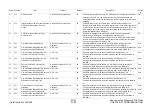
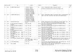
57
60**
Dial tone detection time
(NCU0
PSTN)
0 to 255 sec.
10
If PSTN is selected with Chain=057 and Function=001 (line type) for auto
origination, dial tone detection is attempted from hook-off for the time specified
in this data. When the dial tone is detected or the prescribed time has passed,
dial signal send operation starts.
CE
57
61**
Dial tone detection time
(NCU
PBX)
0 to 255 sec.
04
If PBX is selected with Chain=057 and Function=001(line type) for auto
origination, dial signal send is attempted from hook-off for the time specified in
this data. When the prescribed time has passed, dial signal send operation
starts.
CE
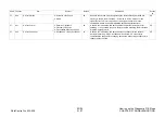
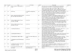
57
62
On-Hook Dial Monitor Timer
0: Infinite 1:60sec 2:90sec 3:180sec
02
57
63
Send time by 1300Hz(NCU0
L Line)
0 to 25500ms (1step=100ms)
40
When L line is selected at Chain=057 and Function=001 (Line type), the
1300Hz single signal can be sent by pressing any key of the keypad. The data
specifies the time to send this signal.
CE
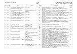
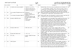
57
70**
PB signal level (NCU0
Outside line)
0 to 20(1step=-1dB) (Reference: 7=-
9dbm or equivalent for FX)
07
When PB is selected at Chain=057 and Function=002(dial type), the push tone
signal will be sent onto the outside line by the level of power as specified.
When the telephone line is not connected, set up a smaller figure.
CE
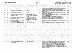
57
71**
PB signal level (NCU0
Extension line)
0 to 20(1step=-1dB) (Reference: 7=-
9dbm or equivalent for FX)
07
When PB is selected at Chain=057 and Function=004(dial type), the push tone
signal will be sent onto the extension line by the level of power as specified.
When the telephone line is not connected, set up a smaller figure.
CE
57
72
PB signal send time by manual send
0 to 255ms
100
When PB is selected at Chain=057 and Function=002(dial type), the push tone
signal will be sent onto the outside line for the specified time by manual send.
Basically, the value need not be changed.
CE
57
78
1 to 15(digit)
05
Destination Check
Set destination check and the number of lower digits for re-origination control.
57
79
0 to 255 sec.
60
Re-origination Timer
Set the re-origination inhibition interval on this timer for re-origination control.
57
80
CNG Send at Manual Transmission
0: Do not send 1: Send
01
Summary of Contents for WorkCentre Pro 423
Page 2: ......
Page 3: ...WorkCentre Pro 423 428 6HUYLFH 0DQXDO...
Page 6: ......
Page 8: ......
Page 9: ...INTRODUCTION...
Page 10: ......
Page 24: ...WorkCentre 423 428 03 02 INTRODUCTION 14 7 Translation of Warnings...
Page 25: ...CHAPTER 1 SERVICE CALL PROCEDURE...
Page 26: ......
Page 28: ...WorkCentre Pro 423 428 1 2 CHAPTER 1 SERVICE CALL PROCEDURE 03 02 1 1 Trimming...
Page 31: ...CHAPTER 2 TROUBLESHOOTING...
Page 32: ......
Page 76: ...WorkCentre Pro 423 428 2 44 CHAPTER 2 TROUBLESHOOTING 03 02 2 3 Level 2 Troubleshooting...
Page 243: ...CHAPTER 3 IMAGE QUALITY TROUBLESHOOTING...
Page 244: ......
Page 273: ...CHAPTER 4 DISASSEMBLY ASSEMBLY AND ADJUSTMENT...
Page 274: ......
Page 329: ...CHAPTER 5 PARTS LIST...
Page 330: ......
Page 415: ...03 02 5 2 Parts List WorkCentre Pro 423 428 5 85 CHAPTER 5 PARTS LIST...
Page 416: ...CHAPTER 6 GENERAL...
Page 417: ......
Page 456: ...CHAPTER 7 ELECTRICAL WIRING DIAGRAMS...
Page 457: ......
Page 476: ...CHAPTER 8 ACCESSORIES...
Page 477: ......
Page 535: ...WorkCentre Pro 423 428 8 58 CHAPTER 8 ACCESSORIES 03 02 8 22 Stamp Kit Red...
Page 536: ...CHAPTER 9 BSD Block Schematic Diagram...
Page 537: ......
Page 541: ......
Page 542: ......
Page 543: ......
Page 544: ......
Page 545: ......
Page 546: ......
Page 547: ......
Page 548: ......
Page 549: ......
Page 550: ......
Page 551: ......
Page 552: ......
Page 553: ......
Page 554: ......
Page 555: ......
Page 556: ......
Page 557: ......
Page 558: ......
Page 559: ......
Page 560: ......
Page 561: ......
Page 562: ......
Page 563: ......
Page 564: ......
Page 565: ......
Page 566: ......
Page 567: ......
Page 568: ......
Page 569: ......
Page 570: ......
Page 571: ......
Page 572: ......
Page 573: ......
Page 574: ......
Page 575: ......
Page 576: ......
Page 577: ......
Page 578: ......
Page 579: ......
Page 580: ......
Page 581: ......
Page 582: ......
Page 583: ......
Page 584: ......
Page 585: ......
Page 586: ......
Page 587: ......
Page 588: ......
Page 589: ......
Page 590: ......
Page 591: ......
Page 592: ......
Page 593: ......
Page 594: ......
Page 595: ......
Page 596: ......
Page 597: ......
Page 598: ......
Page 599: ......
Page 600: ......
Page 601: ......
Page 602: ......
Page 603: ......
Page 604: ......
Page 605: ......
Page 606: ......
Page 607: ......
Page 608: ......
Page 609: ......
Page 610: ......
Page 611: ......
Page 612: ......
Page 613: ......
Page 614: ......
Page 615: ......
Page 616: ......
Page 617: ......
Page 618: ......
Page 619: ......

