WorkCentre Pro 423/428
2-92
CHAPTER 2 TROUBLESHOOTING
03/02
Level 2 Troubleshooting
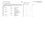
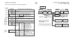
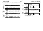
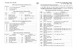
Display
value
(hex)
Reason
Diagnostic information
(May be added)
Number
(decimal)
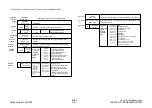
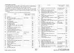
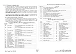
E5
Message mismatching call status
Message type
#101
E6
Recovery by timer expiration *
Timer number
#102
EF
Other procedure error class
-
#111
FF
Other interworking class
-
#127
Classification) #1-31: Normal event, #34-47: Resources not available, #49-63:Service not
available, #65-79: Service not provided, #81-95: Invalid message, #96-111: Procedure error,
#127: interworking
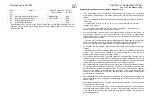
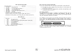
Supplementary Explanations about Reason Display Values
If G4 auto dialling fails to connect the remote terminal, the number may be redialled
automatically. Depending on the reason display value, the redial conditions differ as
follows:
1-1. Only if Reason #3 or #88 is returned after G4 auto dialling, the number is redialled
in G3 mode.
1-2. If Reason 6, 16 to 19, 27, 31, 34, 41, 44, 47, or 102 is returned, the number is
redialled in G4 mode.
1-3. If any other value is returned, the number is not redialled. Depending on the
setting, a transmission failure report may be ejected.
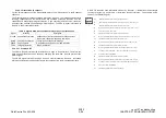
The reason display values indicate the D-channel status (origination, termination, or
disconnection. Reason 16 "normal disconnection" means that the D channel was
disconnected normally. This value is used in case of a B-channel error that occurs after
the remote party is connected.
…Example: If G3 communication through ISDN starts and a DCN signal is received from
the remote terminal, reason 16 is recorded at the DISC signal in ICM protocol monitor
data. In normal status, this reason display is not generated from the network.
#3 indicates that the network cannot connect the remote party despite a connection
request.
…Example: Despite G4 auto dialling, ISDN may not have the corresponding termination
number. The number is then redialled in G3 mode because the remote terminal is
probably not a G4 fax (number not existing on ISDN).
#18 indicates that no ALERT or CONN signal was returned within specified time in
response to a SETUP signal while #19 indicates that an ALERT signal was returned but
not a CONN signal. The ALERT signal indicates that the analogue terminal is now being
called. #19 is used only when the remote terminal is an analogue terminal.
#28 indicates that the switchboard cannot be connected to the remote terminal because
the remote number information is abnormal. For example, the termination number may
be short of digits or contain an abnormal value. If the number is dialled with a space or
dash (-) in the middle, the switchboard may return #28. #28 is also returned if the
number is redialled through a line with an additional service as explained in the manual
or prescribed in the procedure.
#88 indicates that the local terminal does not conform to the transmission capability, low
layer compatibility (LLC) or high layer compatibility (HLC) of the call side declared by a
SETUP signal.
#102 indicates that the Layer 3 timer has reached the prescribed time. The timer may be
on the network or terminal side.
…Example: T303 is a terminal timer. The timer starts when a SETUP signal is received
and stops when a CALLPROC, ALERT, CONN, or RELCOM signal is received. If none
of the signals is received from the remote terminal within four seconds, a DISC signal is
sent with reason #102.
Summary of Contents for WorkCentre Pro 423
Page 2: ......
Page 3: ...WorkCentre Pro 423 428 6HUYLFH 0DQXDO...
Page 6: ......
Page 8: ......
Page 9: ...INTRODUCTION...
Page 10: ......
Page 24: ...WorkCentre 423 428 03 02 INTRODUCTION 14 7 Translation of Warnings...
Page 25: ...CHAPTER 1 SERVICE CALL PROCEDURE...
Page 26: ......
Page 28: ...WorkCentre Pro 423 428 1 2 CHAPTER 1 SERVICE CALL PROCEDURE 03 02 1 1 Trimming...
Page 31: ...CHAPTER 2 TROUBLESHOOTING...
Page 32: ......
Page 76: ...WorkCentre Pro 423 428 2 44 CHAPTER 2 TROUBLESHOOTING 03 02 2 3 Level 2 Troubleshooting...
Page 243: ...CHAPTER 3 IMAGE QUALITY TROUBLESHOOTING...
Page 244: ......
Page 273: ...CHAPTER 4 DISASSEMBLY ASSEMBLY AND ADJUSTMENT...
Page 274: ......
Page 329: ...CHAPTER 5 PARTS LIST...
Page 330: ......
Page 415: ...03 02 5 2 Parts List WorkCentre Pro 423 428 5 85 CHAPTER 5 PARTS LIST...
Page 416: ...CHAPTER 6 GENERAL...
Page 417: ......
Page 456: ...CHAPTER 7 ELECTRICAL WIRING DIAGRAMS...
Page 457: ......
Page 476: ...CHAPTER 8 ACCESSORIES...
Page 477: ......
Page 535: ...WorkCentre Pro 423 428 8 58 CHAPTER 8 ACCESSORIES 03 02 8 22 Stamp Kit Red...
Page 536: ...CHAPTER 9 BSD Block Schematic Diagram...
Page 537: ......
Page 541: ......
Page 542: ......
Page 543: ......
Page 544: ......
Page 545: ......
Page 546: ......
Page 547: ......
Page 548: ......
Page 549: ......
Page 550: ......
Page 551: ......
Page 552: ......
Page 553: ......
Page 554: ......
Page 555: ......
Page 556: ......
Page 557: ......
Page 558: ......
Page 559: ......
Page 560: ......
Page 561: ......
Page 562: ......
Page 563: ......
Page 564: ......
Page 565: ......
Page 566: ......
Page 567: ......
Page 568: ......
Page 569: ......
Page 570: ......
Page 571: ......
Page 572: ......
Page 573: ......
Page 574: ......
Page 575: ......
Page 576: ......
Page 577: ......
Page 578: ......
Page 579: ......
Page 580: ......
Page 581: ......
Page 582: ......
Page 583: ......
Page 584: ......
Page 585: ......
Page 586: ......
Page 587: ......
Page 588: ......
Page 589: ......
Page 590: ......
Page 591: ......
Page 592: ......
Page 593: ......
Page 594: ......
Page 595: ......
Page 596: ......
Page 597: ......
Page 598: ......
Page 599: ......
Page 600: ......
Page 601: ......
Page 602: ......
Page 603: ......
Page 604: ......
Page 605: ......
Page 606: ......
Page 607: ......
Page 608: ......
Page 609: ......
Page 610: ......
Page 611: ......
Page 612: ......
Page 613: ......
Page 614: ......
Page 615: ......
Page 616: ......
Page 617: ......
Page 618: ......
Page 619: ......

