WorkCentre Pro 423/428
2-106
CHAPTER 2 TROUBLESHOOTING
03/02
Level 2 Troubleshooting
2.3.3 Super G3 Fax
2.3.3.1 Super G3 Fax
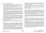
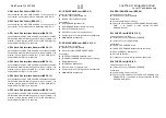
In 1996, ITU-T recommended Super G3 Fax.
Super G3 Fax featuring 28.8 kbps communication has the modem capabilities of V.8 and
V.34. The protocol consists of V.8 and V.34 and optionally supports 33.6 kbps. Super G3 Fax
enables a fax to communicate with models of other manufacturers and also with the
conventional 14.4 kbps and 9600 bps faxes.
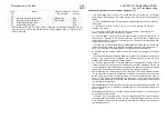
l
Super G3 Fax communication is recorded as SG3 in the mode column of a report.
l
Super G3 Fax transmits image information in Error Correction Mode (ECM).
l
V.34 is a standard for modems from 28.8 kbps (optionally, 33.6 kbps) to 2400 bps.
Prior to the V.34 standard, V.8 prescribes a procedure for selecting optimum mode
according to the line status.
For communication with the conventional faxes as well as V.34 (28.8 kbps) ones, Super G3
Fax has also the capabilities of V.17 (14.4 kbps) and V.29/V.27ter (9600/4800 bps). The V.8
standard prescribes a procedure for checking the line status and selecting an optimum speed.
l
V.34 does not use the TCF signal in phase B.
l
In V.34, the command (NSF, DIS, and other) speed for the conventional procedure
section is 1200 bps.
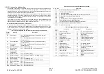
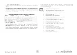
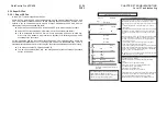
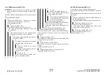
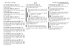
Signal names and contents
Dial
Termination
Calling (CNG) signal: To indicate a communication function,
the local terminal sends this signal continuously until the
ANSam signal is received. This signal is not recorded in trace
data.
For manual transmission, a terminal sends "CI" as the V.8
calling signal.
Also if the protocol enters phase B without detecting ANSam
and DIS V.8 capability is enabled (bit 6=1), the origination
side sends CI and returns to the V.8 procedure in Super G3
mode.
ANSam (response signal): The fax stops after sending a 2100
Hz signal modulated by 15 Hz for 4 continuous seconds or
when CM is detected. If the fax does not support Super G3
mode, CED is detected.
Call menu (CM) signal: This 300 bps signal (*) declares
modem mode available at the local terminal.
Common menu (JM) signal: This 300 bps signal (*) declares
modem mode available at the local and remote terminals and
stops when CJ is detected. (For the FIFs of the CM and JM
signals, see No.2 "V.8 CM/JM Signal.")
CM end (CJ) signal: This 300 bps signal indicating JM check
and CM end is a three-octet string of 0.
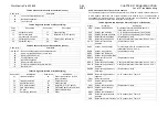
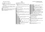
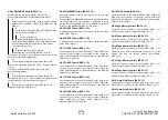
[V34ph2]
[V34ph3]
[V34ph4]
V.34 Phase 2 (ph2): Probing
The line characteristics are measured using the probing
signal.
V.34 Phase 3 (ph3): Equalizer training
The modem equalizer is set using the TRN signal.
V.34 Phase 4 (ph4): Final training
The signal speed is determined.
(V.34 Phase 1 means the V.8 procedure.)
The modems of the local and remote terminals automatically
execute this section (Phases 2 to 4) to determine the send
level, equalizer, and modulation speed. The values
determined here have priority over the NSF/DIS contents.
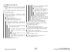
NSF
DIS
NSS
CFR
TRN
TRN
CPIX
CPIX
PPS.EOP
MCF
DCN
LOCAL
REMOTE
CNG
ANSam
CM
JM
CJ
V.8
V.34
Phase B
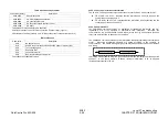
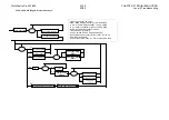
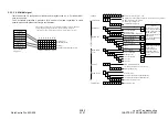
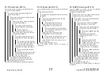
Sample Protocol (T.30) Trace of Super G3 Fax
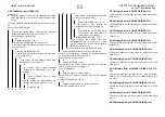
The V.34 modem has a command channel (low-
speed channel for NSF, DIS, and other
commands) and a primary channel (high-speed
channel for image and training signals).
Phase C
Phase D
*Phases B to E belong to the facsimile
procedure.
Phase E
Summary of Contents for WorkCentre Pro 423
Page 2: ......
Page 3: ...WorkCentre Pro 423 428 6HUYLFH 0DQXDO...
Page 6: ......
Page 8: ......
Page 9: ...INTRODUCTION...
Page 10: ......
Page 24: ...WorkCentre 423 428 03 02 INTRODUCTION 14 7 Translation of Warnings...
Page 25: ...CHAPTER 1 SERVICE CALL PROCEDURE...
Page 26: ......
Page 28: ...WorkCentre Pro 423 428 1 2 CHAPTER 1 SERVICE CALL PROCEDURE 03 02 1 1 Trimming...
Page 31: ...CHAPTER 2 TROUBLESHOOTING...
Page 32: ......
Page 76: ...WorkCentre Pro 423 428 2 44 CHAPTER 2 TROUBLESHOOTING 03 02 2 3 Level 2 Troubleshooting...
Page 243: ...CHAPTER 3 IMAGE QUALITY TROUBLESHOOTING...
Page 244: ......
Page 273: ...CHAPTER 4 DISASSEMBLY ASSEMBLY AND ADJUSTMENT...
Page 274: ......
Page 329: ...CHAPTER 5 PARTS LIST...
Page 330: ......
Page 415: ...03 02 5 2 Parts List WorkCentre Pro 423 428 5 85 CHAPTER 5 PARTS LIST...
Page 416: ...CHAPTER 6 GENERAL...
Page 417: ......
Page 456: ...CHAPTER 7 ELECTRICAL WIRING DIAGRAMS...
Page 457: ......
Page 476: ...CHAPTER 8 ACCESSORIES...
Page 477: ......
Page 535: ...WorkCentre Pro 423 428 8 58 CHAPTER 8 ACCESSORIES 03 02 8 22 Stamp Kit Red...
Page 536: ...CHAPTER 9 BSD Block Schematic Diagram...
Page 537: ......
Page 541: ......
Page 542: ......
Page 543: ......
Page 544: ......
Page 545: ......
Page 546: ......
Page 547: ......
Page 548: ......
Page 549: ......
Page 550: ......
Page 551: ......
Page 552: ......
Page 553: ......
Page 554: ......
Page 555: ......
Page 556: ......
Page 557: ......
Page 558: ......
Page 559: ......
Page 560: ......
Page 561: ......
Page 562: ......
Page 563: ......
Page 564: ......
Page 565: ......
Page 566: ......
Page 567: ......
Page 568: ......
Page 569: ......
Page 570: ......
Page 571: ......
Page 572: ......
Page 573: ......
Page 574: ......
Page 575: ......
Page 576: ......
Page 577: ......
Page 578: ......
Page 579: ......
Page 580: ......
Page 581: ......
Page 582: ......
Page 583: ......
Page 584: ......
Page 585: ......
Page 586: ......
Page 587: ......
Page 588: ......
Page 589: ......
Page 590: ......
Page 591: ......
Page 592: ......
Page 593: ......
Page 594: ......
Page 595: ......
Page 596: ......
Page 597: ......
Page 598: ......
Page 599: ......
Page 600: ......
Page 601: ......
Page 602: ......
Page 603: ......
Page 604: ......
Page 605: ......
Page 606: ......
Page 607: ......
Page 608: ......
Page 609: ......
Page 610: ......
Page 611: ......
Page 612: ......
Page 613: ......
Page 614: ......
Page 615: ......
Page 616: ......
Page 617: ......
Page 618: ......
Page 619: ......

