background image

03/02

Level 2 Troubleshooting

WorkCentre Pro 423/428

2-109

CHAPTER 2 TROUBLESHOOTING

2.3.3.5  Troubleshooting of Super G3 Fax

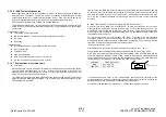
Super G3 fax uses analogue communication and its troubleshooting is basically the same as
that of the conventional G3 Fax.  However, since the communication speed and procedure are
different, this section describes troubleshooting unique to Super G3 mode.

Super G3 Fax realizes communication up to 28,800 bps by a modem of the V.34 standard.
The speed can be optionally increased up to 33,600 bps.

The conventional speed is 14,400 bps (V.17).  To realize the high-speed communication of
V.34, the conventional data transmission rate must be more than doubled.  Therefore, the
telephone line quality will affect communication more than ever.  Even a telephone line
available for error-free communication at 14,400 or 9600 bps may cause an error in Super G3
communication.

An ordinary analogue public line shows a good frequency characteristic in a band from 300 to
3,400 Hz.  In Super G3 communication, the communication speed may differ if only the
direction of communication is reversed without changing the parties or the telephone line.  In
this communication, the transmission side determines the communication speed according to
the result of line quality measurement by the probing function in the V.34 procedure and the
probing result varies each time the direction of communication is reversed.  In other words,
Super G3 mode cannot always achieve the maximum speed (33,600 bps).  In most cases, the
Super G3 communication speed is 21,600 bps or more.

The conventional fax up to 14,400 bps uses half-duplex communication where signals are
sent alternately.  Super G3 fax, however, uses full-duplex communication of a different
communication procedure.  In full-duplex communication, both faxes issue signals together.
While sending signals, each fax monitors signals from the other fax.  The communication
status can be supervised by monitoring a line for sounds in the conventional fax
communication but not in Super G3 communication.  If a communication error occurs, the
analysis of protocol monitor data is necessary more than ever and the trace data of both the
transmitter and receiver may be compared often.

Notes on Super G3 troubleshooting

ECM:  ECM is essential for Super G3 communication.  If the ECM function is OFF, even a fax
supporting Super G3 mode will use not V.34 but V.17/V.29 (14,000/9600 bps) for
communication.

Communication procedure:  The Super G3 communication procedure consists of V.8 and
V.34.  The V.8 procedure is used to check the Super G3 mode capability and to determine the
communication speed.  Once the V.8 procedure has terminated normally, Super G3 fax
changes to the V.34 procedure and sends image information by the V.34 procedure.  The V.34
procedure uses the same commands as the G3 procedure (V.17/V.29 or other) and the
protocol trace data is also almost the same.  However, the actual communication type is full
duplex and the command transmission speed is 1200 bps.

The V.8 procedure uses the tonal signals of CNG or CI sent from an originating terminal for
manual transmission and ANSam sent from a terminating terminal.  If the line receives noises
or the signal level is low, an error occurs because the remote terminal cannot recognize the
tonal signals correctly.  For this check, protocol data of the remote terminal is checked to see
whether signals sent from the local terminal are recorded (as recorded in the local trace data).

The V.34 procedure is executed in the order of phases 2, 3, and 4 and [V34ph2], [V34ph3],
and [V34ph4] are recorded in the protocol trace data.  Once phase 4 has terminated normally,
the procedure changes to phases B, C, D, and E.  For troubleshooting in these phases,
reference the conventional procedure.

If the line receives noises or the signal level is low, the procedure may not progress smoothly.
If phases 2, 3, and 4 are repeated, [V34ph2], [V34ph3], and [V34ph4] are recorded again and
again in the protocol trace data.  If an error occurs in phase 2, [V34ph2] is recorded but
[V34ph3] and [V34ph4] are not.

In both of the above two cases, the analog characteristics of the telephone line are defective
or the send level is inappropriate.

Send level:  Since Super G3 Fax uses analog communication, the signal level is very
important.  Especially, the signal to noise level (S/N) ratio is the key.  For correct signal
detection, a certain S/N ratio is necessary.  The protocol data may indicate that the remote
terminal sends the same signal repeatedly or does not advance to the next procedure.  This
means that the remote terminal cannot recognize signals from the local terminal.  In this case,
change the send level.  If the noise level does not change, raising the send level should
increase the S/N ratio.  When changing the send level, vary the send level a little (1 or 2 dB)
and find the best value by trying communication several times.

If a digital line (ISDN/corporate digital leased line) or digital equipment (digital PBX/TA) is in
use, raising the level too high will cause a waveform disorder to an analog signal and disable
normal communication (high-level signal waveforms are deformed at analog-digital
conversion).  Under this kind of line environment, lowering the send level will establish good
communication.

Speed:  The maximum speed is 33,600 bps in Super G3 mode.  In domestic PSTN
communication, however, the actual speed is 31,200 to 21,600 bps in most cases.  If the line
status is extremely bad, the speed may be even as low as 9600 bps.  The communication
speed is determined by a transmission terminal according to the result of phase 2 in V.34.
Therefore, even when the same line is used, the communication speed varies with the
transmission terminal.

Line frequency characteristic (F characteristic):  The characteristic of a telephone line about
frequency is called "frequency characteristic."   The characteristic ideally should be uniform in
the speech band from 300 to 3400 Hz but usually deteriorated at at high and low frequencies
of a public line (attenuation distortion or signal delay not affecting a speech).  The longer the
ground distance (more precisely, the line distance of the analogue section) becomes, the
worse the deterioration becomes. Compared with ordinary voice or G3 Fax communication,
Super G3 communication is greatly affected by the frequency characteristic.  Even a line
available for normal communication at 14,000 or 9600 bps may cause errors in Super G3
communication.  Since most corporate leased lines (digital lines) use voice compression, their
frequency characteristics are worse than those of NTT public lines.  Therefore, the error
occurrence rate goes high in Super G3 communication.

Summary of Contents for WorkCentre Pro 423

Page 1: ...Transmittal Page 3URGXFW RUN HQWUH 3UR 7LWOH 6HUYLFH 0DQXDO 3DUW 1XPEHU 3 6WDWXV QWLDO VVXH DWH 0DUFK...

Page 2: ......

Page 3: ...WorkCentre Pro 423 428 6HUYLFH 0DQXDO...

Page 4: ...nd destroy the superseded page Be careful of handling to avoid missing or damaging the manual Revision and Modification Information When design changes or revisions relating to this service manual occ...

Page 5: ...sion Control List Product WorkCentre Pro 423 428 Title WorkService Manual Part Number 708P86749 Revision March 2002 RFXPHQWDWLRQ DYDLODEOH DUG RS 3 3 YHUVLRQ RQ 520 3 OO SDJHV LQ WKLV PDQXDO DUH UHYLV...

Page 6: ......

Page 7: ...nslation of Warnings SECTION 1 SERVICE CALL PROCEDURES SECTION 2 TROUBLESHOOTING SECTION 3 IMAGE QUALITY TROUBLESHOOTING SECTION 4 DISASSEMBLY ASSEMBLY AND ADJUSTMENT SECTION 5 PARTS LIST SECTION 6 GE...

Page 8: ......

Page 9: ...INTRODUCTION...

Page 10: ......

Page 11: ...8 1 INTRODUCTION Contents 1 Scope of this Document 2 2 How to Use this Manual 2 2 1 Organisation of this Manual 2 2 2 Revision Information 2 3 Terms and Symbols 3 4 Abbreviations 4 5 Safety Informatio...

Page 12: ...ssembly assembly adjustment and replacement of components Section 5 Parts List This Section contains lists of parts spared and otherwise Section 6 General This Section provides the general information...

Page 13: ...ghlight a procedure practice condition or statement Used to alert you to a procedure which if not strictly observed could result in damage to the printer or equipment Used when work procedures and rul...

Page 14: ...TR Bias Transfer Roll BUR Back Up Roll CART Cartridge CCW Counter Clock Wise CL Clutch CLN Cleaning or Cleaner CLK Clock CR Charge Roll CRU Customer Replaceable Unit CRUM CRU Monitor CW Clock Wise DB...

Page 15: ...o dispose of the cartridge into the municipal waste Check with the local waste officials for details on recycling options or the proper disposal procedures Safety Icons The following safety icons are...

Page 16: ...8 6571 Electronic mail EH S at Doris Bush usa xerox com Fax EH S at 1 716 422 7734 intelnet 8 222 7734 For incidents in Europe and Developing Markets East Middle East Africa India China and Hong Kong...

Page 17: ...letzungen oder Stromschl gen f hren kann Der Umgang mit beweglichen Bauteilen kann zu ernsthaften k rperlichen Verletzungen f hren AVISO Apague la m quina y desconecte el cable de potencia de la red a...

Page 18: ...or el Departamento de Salud y Servicios Humanos de los Estado Unidos como un producto de la Clase 1 Esto significa que es un producto l ser que no emite radiaci n l ser peligrosa durante ninguno de su...

Page 19: ...den Vorschriften entsprechend ausf hren Das nicht den Vorschriften entsprechende Bedienen der Ger ts oder ndern bestimmter Ger teeinstellungen kann zum Kontakt mit unsichtbarer Laserstrahlung f hren...

Page 20: ...age if looked at directly DANGER Les proc dures d entretien doivent tre rigoureusement suivies comme indiqu dans la documentation L utilisation de commandes ou de r glages autres que ceux sp cifi s da...

Page 21: ...tra el l ser cuando vea este s mbolo Chapter 4 Dissasembly and Assembly Procedures Adjustments WARNING Switch off the machine and disconnect the power cord DANGER Isoler la machine et d brancher le co...

Page 22: ...p se 46 kg 101 lb Deux personnes sont requises pour soulever ce module Faire tr s attention en le soulevant ATTENZIONE Il complessivo IOT pesa 46 Kg Sono necessarie due persone per alzarlo Fare molta...

Page 23: ...der Stromquelle entfernen AVISO Apague la m quina y desconecte el cable de potencia WARNING The weight of the DADF assembly is 8 6 kg 18 6 lb Use great care when lifting DANGER Le chargeur de documen...

Page 24: ...WorkCentre 423 428 03 02 INTRODUCTION 14 7 Translation of Warnings...

Page 25: ...CHAPTER 1 SERVICE CALL PROCEDURE...

Page 26: ......

Page 27: ...03 02 Contents WorkCentre Pro 423 428 1 1 CHAPTER 1 SERVICE CALL PROCEDURE Contents 1 1 Trimming 3 1 1 1 Trimming Procedure 3 1 1 2 Consumables and consumable parts 3 1 1 3 Trimming Check List 4...

Page 28: ...WorkCentre Pro 423 428 1 2 CHAPTER 1 SERVICE CALL PROCEDURE 03 02 1 1 Trimming...

Page 29: ...copying and feeding at trimming and replace necessary items The history can be checked in Diag C E mode See Chapter 2 Diagnostic Mode Drum Unit Consumables Replacement interval Remarks Drum Unit 24K...

Page 30: ...glass back surface and mirror lens cleaning a Clean with a lint free cloth 4 1 DADF cleaning Platen cleaning b Clean with a damp cloth 4 2 DADF cleaning Feed Roll cleaning or replacement a c 10 5 2 C...

Page 31: ...CHAPTER 2 TROUBLESHOOTING...

Page 32: ......

Page 33: ...ion of Common Terms 101 2 3 2 8 Installation Notes 103 2 3 2 9 Cases of Parameter Setting Error or Mismatch 105 2 3 3 Super G3 Fax 106 2 3 3 1 Super G3 Fax Introduction 106 2 3 3 2 V 8 CM JM Signal 10...

Page 34: ...connectors on them for proper connections before replacements l When it is impossible to resolve problems with the Fax contact the national Technical Specialists and the local support centre 1 Glossar...

Page 35: ...ective actions for other FIPs or BSDs Chapter 9 Or Try communication with NSC Are communications conducted normally Y N Have you made communications tests with NSC twice Y N Take corrective action for...

Page 36: ...code Status Code Status Description Corrective Action Ref BSD U0 01 4001 DCSYS Software failure Undefined interrupt such as Break command and 0 subtraction Power OFF ON 3 1C U0 02 4002 DCSYS Software...

Page 37: ...not over 5 degrees continuous three times in 5 seconds during warm up POWER OFF ON 10 2 Status Code Status Description Corrective Action Ref BSD U6 01 4061 Memory error at Power ON MCU SW PWB Memory...

Page 38: ...r system Communication Fail Communication not established between MCU SW PWB and IIT IPS PWB POWER OFF ON Check connectors 3 1A Status Code Status Description Corrective Action Ref BSD U8 3 4483 LAMP...

Page 39: ...Finisher Fault COMPILE MOTOR Fail COMPILE HP sensor not ON OFF within specified time POWER OFF ON 12 8 H5 82 4582 Finisher Fault Stapler Motor Fail Staple HP sensor not ON at stapling POWER OFF ON 12...

Page 40: ...SENSOR OFF Remove paper 8 5 10 3 E1 6 4E14 JAM at REGI SNR Paper remaining on REGI SENSOR Remove paper 8 5 Status Code Status Description Corrective Action Ref BSD E3 1 4E31 JAM at FUSER FUSER EXIT S...

Page 41: ...ime after FEED IN SENSOR ON Remove document 5 4 Status Code Status Description Corrective Action Ref BSD A2 3 4A23 DADF document jam regi section REGI SENSOR or READ SENSOR not OFF within specified ti...

Page 42: ...PILER Close theCover 12 1 F7 3 4F73 FINISHER Interlock Open COMPILER TOP COVER is open Close theCover 12 2 F8 1 4F81 FINISHER Interlock Open FIN SHER Interlock is open Close theCover 12 2 J1 2 4B12 No...

Page 43: ...3 1 4 V Code List V Code Internal code Description Corrective Action V0 00 F000 Main CPU exception processing error Reset Initial SSP Replace M F MAIN PWB V0 00 F004 Main CPU exception processing err...

Page 44: ...g command to clock control function Check replace M F MAIN PWB DRAM PAGE MEMORY and MMB V0 07 8341 Wrong device channel instruction Check replace M F MAIN PWB DRAM PAGE MEMORY and MMB V Code Internal...

Page 45: ...MAIN PWB PAGE MEMORY and MMB V1 02 8360 VCEPDMA transfer underrun Check replace M F MAIN PWB VCEP V1 02 8361 DMA_CH1 handler open failure Check replace M F MAIN PWB and MMB V1 02 8362 DMA_CH1 handler...

Page 46: ...ved from G3M Check M F MAIN PWB and G3M board for connections Replace M F MAIN PWB or G3M board V Code Internal code Description Corrective Action V1 07 83C0 Illegal channel number received by G3 chan...

Page 47: ...12 8421 Command interface from M F MAIN PWB to ICM is busy Check M F MAIN PWB and G4 ICM board for connections Replace M F MAIN PWB or G4 ICM borad V Code Internal code Description Corrective Action...

Page 48: ...F MAIN PWB V2 00 81B1 Stop processing failure SS_REQ_STOP processing failure Check replace M F MAIN PWB PAGE MEMORY and MMB V2 00 81B2 Illegal event received by Process Monitor Task SS_MEMORY_FULL Ch...

Page 49: ...CONTROL PANEL or clear memory V2 04 8132 Job registration table overflow in information area jobmgr for job control and management by panel Check replace M F MAIN PWB PAGE MEMORY MMB and CONTROL PANEL...

Page 50: ...M F MAIN PWB V4 03 8002 Error detected by OS Wrong TCB address Check M F MAIN PWB PAGE MEMORY and MMB Replace M F MAIN PWB V Code Internal code Description Corrective Action V4 03 8003 Error detected...

Page 51: ...MORY and MMB V6 06 8251 Invalid event notice to File job deletion task Check replace M F MAIN PWB PAGE MEMORY and MMB V Code Internal code Description Corrective Action V6 06 8252 a_post failure Faile...

Page 52: ...MAIN PWB or G3M software bug Replace the software with the latest version Replace the G3M or M F MAIN PWB V Code Internal code Description Corrective Action V7 00 850A Failure to convert physical addr...

Page 53: ...V7 00 8578 Specified TPCB address not found Check replace G3M and M F MAIN PWB V7 00 8579 Specified TCB address not found Check replace G3M and M F MAIN PWB V Code Internal code Description Corrective...

Page 54: ...ntrol handler abnormal Opening Check M F MAIN PWB and G4M board for connections Replace M F MAIN PWB or G4M board V7 03 89C4 G4M transputer control handler abnormal Data Check M F MAIN PWB and G4M boa...

Page 55: ...3 data interface idle timeout Check M F MAIN PWB and G3M board for connections Replace M F MAIN PWB or G3M board V7 08 85E4 Event issue failure by codec Check replace M F MAIN PWB Retry V7 08 85E5 No...

Page 56: ...twork and line K0 03 086A Subscriber No of remote terminal changed ISDN Check remote terminal K0 03 086B Not used Recovery of unselected user from disconnection ISDN Check network and line K Code Inte...

Page 57: ...A5 Selected functions are restrained by system data Check system data restraining functions K5 04 00A0 Wrong job requesting parameter Check host s job requesting parameter K Code Internal Code Error D...

Page 58: ...channel abortion Check P ESS print queue status Initialize or replace HDD K Code Internal Code Error Description Corrective Action K5 23 062C End of transfer job due to P ESS internal HDD write error...

Page 59: ...NCU K Code Internal Code Error Description Corrective Action K6 04 0547 Third dial tone couldn t be detected before dialing DT3 can t be detected Connect line properly Change line setting Check replac...

Page 60: ...be detected after dialing PBX RBT can t be detected Connect line properly Change line setting Check replace MAIN modem and NCU K6 07 027A Abortion of transfer job for immediate host transmission due t...

Page 61: ...line setting Check replace MAIN modem and NCU K Code Internal Code Error Description Corrective Action K6 07 056B Congestion tone was detected after dialing CT1 detected Check switchboard Connect line...

Page 62: ...after detection of RBT Ring back tone after dialing PBX BT detected Connect line properly Change line setting Check replace MAIN modem and NCU K6 07 0589 Congestion tone was detected after detection...

Page 63: ...SS Check the remote terminal K8 02 027C E mail received data containing data of format not supported by MF SYS Check the remote terminal K Code Internal Code Error Description Corrective Action K8 03...

Page 64: ...ce MMB board D1 42 3102 OM parts are not good OM_ERROR Replace OPTION MEMORY board D1 43 3103 OPTION MOTHER board part are not good OPMOT_ERROR Replace OPTION MOTHER board D1 44 3104 M F MAIN PWB part...

Page 65: ...ul in G4M1 ICM Loop Test G4M1_ICM_LOOP_ERROR Check replace G4M1 G4 ICM and OPTION MOTHER board Check connections D2 40 3125 Unsuccessful in G3M0 NCU Loop Test G3M0_NCU_LOOP_ERROR Check replace M F MAI...

Page 66: ...e problem by the activity report For a repeatable problem grasp signal send receive results by outputting the protocol monitor This leads to operation efficiency Resolve a X Code problem by isolating...

Page 67: ...complete after error free transmission and reception Send Complete Transmission to PESS is complete but arrival at the remote party is not sure Busy The redial count has exceeded the limit Auto Resen...

Page 68: ...ned X Undefined CRC error detected Undefined Undefined Undefined Carrier puts a 1 sec Pause during receiving pixels Undefined An instantaneous pause during receiving pixels Undefined Undefined Undefin...

Page 69: ...End of message ECM EOR EOP End of re send End of Procedure ECM EOR MPS End of re send Multi pages signal ECM EOR NULL End of re send Partial page border ECM EOR PEOM End of re send Procedure interrupt...

Page 70: ...us CmlOReq CML OFF request DialCon Dial confirmation DialReq Dial request HkOffDt Hook off detection HkOnDt Hook on detection LnHAInd Line hold abandon indication LnHdInd Line hold indication LnHdRes...

Page 71: ...n DiscRes Line Disconnection response SeOpReq Request for session open SeOpCon Session Open confirm SeClReq Request for session close SeClCon Session closed confirm SeClInd Session closed indication S...

Page 72: ...NR Receive not ready RQ Reset request RI Reset instruction RF Reset confirm IT Interrupt IF Interrupt confirm DIG Diagnostic GQ Registration request GF Registration confirm Unknown Undefined COMWTOUT...

Page 73: ...connection CallCon Line Connection confirm CallInd Line Connection indication CallRes Line Connection response DiscReq Request for line disconnection DiscCon Line Disconnected confirm DiscInd Line Di...

Page 74: ...sage SUSPREJ Suspension Reject message DISC Disconnection message Signal Description RELEASE Release message RELCOMP Release Complete message INFO Addition Information message NOTIFY Notify message RE...

Page 75: ...eq Request for line disconnection DiscCon Line Disconnected confirm DiscInd Line Disconnected indication DiscRes Line Disconnection response TrcReq Trace request TrcCon Trace confirmation SlpReq Sleep...

Page 76: ...WorkCentre Pro 423 428 2 44 CHAPTER 2 TROUBLESHOOTING 03 02 2 3 Level 2 Troubleshooting...

Page 77: ...non standard irradiation light Set 0 for CIE standard irradiation light D50 Valid only when bit 68 is 1 C 75 GAR Colour fax non standard gamut range Set 0 for the standard range Valid only when bit 68...

Page 78: ...ng File during execution of File overwrite processing Check replace M F MAIN PWB and MMB X0 27 03D9 File to be opened doesn t exist Check replace M F MAIN PWB and MMB X0 27 03DC Write open was attempt...

Page 79: ...k replace M F MAIN PWB and MMB X0 27 0442 Header Print Area Read Failure Check replace M F MAIN PWB and MMB X0 27 0443 Data Write Processing NG Check replace M F MAIN PWB and MMB X0 27 0444 Data Read...

Page 80: ...Check M F MAIN PWB and MCU SW PWB for connections Replace M F MAIN PWB or MCU SW PWB X0 29 0281 ERR_PR_DCREAD_NG Parameters that don t exist were attempted to read from DC X Code Internal Code Error D...

Page 81: ...r between Line A external line call and connect when 1300 Hz signal reached Re dial Check replace MAIN Modem and NCU X Code Internal Code Error Description Corrective Action X0 40 0537 Overrun Retry R...

Page 82: ...place M F MAIN PWB Retry X2 23 051C Carrier disconnected Retry Check the remote terminal line Replace MAIN Modem X Code Internal Code Error Description Corrective Action X2 33 02C0 In Remove Maintenan...

Page 83: ...l line X2 75 053E HDLC frame send error Retry Replace MAIN Modem X3 00 0919 G4 Data link can t be set up Check the remote terminal line Check replace G4M PWB X Code Internal Code Error Description Cor...

Page 84: ...eived Check the remote terminal X3 35 097D G4 Mismatched density was instructed to be received Check the remote terminal X Code Internal Code Error Description Corrective Action X3 35 097E G4 Mismatch...

Page 85: ...e confirm message time out Check the line Check replace G4 ICM PWB X3 64 0841 Not used Reception of Restart confirm message time out Check the line Check replace G4 ICM PWB X Code Internal Code Error...

Page 86: ...ived ID set message which includes the same value as the present TEI equivalent Toki EM_TEI_GET 88C3 Check network and line Check replace G4 ICM PWB X3 74 0826 TEI control task received TEI ID release...

Page 87: ...HDD 3 Replace ESS PWB 003 375 N7 30 DC_SYS_DOWN status received Ready to print 003 376 N7 30 Command error status received Ready to print 003 377 N7 30 Essential sent command was rejected by IOT COMMA...

Page 88: ...Refer to General purpose Sensor FIP and check Sensor 003 966 ATS APS No Destination Error Refer to General purpose Sensor FIP and check Sensor 003 985 Check SMH pause Check Tray5 xxxx Check the paper...

Page 89: ...ase the PC memory capacity 016 720 PCL Command Error AP specification Error resolved PCL Command Error Cancel and execute the job again Chain Link Description LCD display Job log Corrective Action 016...

Page 90: ...ace HDD Chain Link Description LCD display Job log Corrective Action 016 743 Job template spool server setting error Error resolved Job template server setting error 016 744 Job template spool server...

Page 91: ...image conversion by S Formatter Error resolved Image conversion error Not needed 016 777 HDD access error during image conversion by S Formatter Error resolved Hard disk error Not needed Chain Link D...

Page 92: ...according to the label inside DADF unit 2 Close the unit 050 104 1 Slide the upper right unit of the main unit and remove the jammed paper 2 Close the unit 1 Pull out Paper tray 1 and remove the jamm...

Page 93: ...int Chain Link Description LCD display Job log Corrective Action 081 701 Invalid Fax number FAXC_EInvalidCallNo Argument Error Error resolved Fax number error 081 702 Invalid Fax communication paramet...

Page 94: ...from confidential box FAXC_EMBDocNotRetrieve d Mailbox Error Error resolved Confidential box document fetch error 081 719 Unable to store document in specified confidential box FAXC_EMBDocNotStored Ma...

Page 95: ...ct and insert the ESS RAM DIMM 1 2 Replace ESS RAM DIMM 1 3 Replace ESS PWB 116 317 N6 10 ESS ROM DIMM 1 Check Fail Ready to print 1 Extract and insert the standard ROM DIMM 2 Replace standard ROM DIM...

Page 96: ...6 343 N9 50 MF SYS communication error detected by JT monitor Ready to print 116 344 N9 51 Critical error detected by MFIO Ready to print 1 Power OFF ON 2 Replace ESS PWB Chain Link Description LCD di...

Page 97: ...73 AutoSW critical error Ready to print 1 Reinstall the ESS software 2 Replace ESS PWB 116 376 N9 66 Port 9100 Software Fail Ready to print Chain Link Description LCD display Job log Corrective Actio...

Page 98: ...ied AP specification PCL Memory Low Page Simplified Disable unnecessary ports Adjust various buffer memory sizes Add extension memory 116 740 Numeric operations beyond limit in interpreter Numeric ope...

Page 99: ...receive interrupt 8183 EM_PNLIF_INTRILLEGAL An illegal interrupt occurred with PNL I F Check M F MAIN PWB and CONTROL PANEL for connections Replace M F MAIN PWB or CONTROL PANEL Internal Code Error De...

Page 100: ...CU SW PWB M F MAIN PWB or UI M F MAIN PWB connector then reboot the M C If there are any system data with wrong value clear them and reboot the M C Internal Code Error Description Corrective Action 81...

Page 101: ...B or CONTROL PANEL 82C0 Invalid box number for box deletion and all document deletion Internal Code Error Description Corrective Action 8364 TCB Error EM_DMA_TCB_ERROR Check M F MAIN PWB for connectio...

Page 102: ...Replace HDD Internal Code Error Description Corrective Action 8715 WRITE command reexecution failure EM_HD_WRITE_RETRY Check the hardware Replace HDD 8716 TEST UNIT READY command reexecution failure...

Page 103: ...0 inhibited from use was detected Check M F MAIN PWB and ROM Replace CONTROL PANEL Internal Code Error Description Corrective Action 8C0D Selected ECB address can t be found Check M F MAIN PWB and RO...

Page 104: ...8C45 The job applicable doesn t exist on Job Manager Table Check M F MAIN PWB and ROM Replace CONTROL PANEL 8C46 The job can t be registered Check M F MAIN PWB and ROM Replace CONTROL PANEL 8C47 No b...

Page 105: ...PWB connections Check M F MAIN PWB and ROM Replace CONTROL PANEL Internal Code Error Description Corrective Action 8C75 No response is made after pnlif mon is attached at M C initialization Check CONT...

Page 106: ..._HD_INIT_NG S W bug 8DD2 HDD not ready EM_HD_NOT_READY Set HDD ready 8DE0 DRAM error during file control information read Check replace the hardware 8DE1 DRAM error during directory control informatio...

Page 107: ...corresponding protocol monitor data is ejected for checking and analyzing signal exchange and contents Then corrective and recovery actions are taken according to the results Details of the signals ar...

Page 108: ...protocol by re communication Judgment Action work D channel 0 HUURU No 1 Yes Yes Error Code D channel B channel Comm mode K0 00 03 K6 03 07 K9 01 X3 60 ICM K7 07 X3 00to40 G4 mode K6 0 to 07 K7 00 to...

Page 109: ...rminator 100 ohms ISDN allows up to eight terminals to be connected to a line The terminals are connected through a bus and the farthest connection block or terminal requires a terminator If no termin...

Page 110: ...n Appli cation Operator ALEART CONN Connection confirmation C Call request Req est Connection indication INFO 4 UA CALLPROC INFO 2 INFO 3 INFO 4 SETUP Termination notice UI CONN CONNACK Response R TEI...

Page 111: ...tation Appli cation Session Trans port Net work Data Link Physi cal ISDN net Physi cal Data Link Net work Trans port Session Presen tation Appli cation Operator DISC RELEASE DISC UA DISC RELCOMP DISC...

Page 112: ...DN BRI Physi cal Data Link Net work Trans port Session Presen tation Appli cation Operator D channel communication See the D channel sequence SQ SF CR G4 Start TCR 011111 SAB CC 011111 TC Pre D Doc Pr...

Page 113: ...ork Trans port Session Presen tation Appli cation Operator UA RDE CF Text U Text U Text U I DT TDT CDUI TextU I DT TDT CDUI TextU I DT TDT CDUI TextU CDE I DT TDT CDE I DT TDT RDEP I DT TDT CSE I DT T...

Page 114: ...40 99 CONN 08018107 9 40 99 CONNACK 0801010F 9 45 66 DISC 0801014508028090 9 45 74 RELEASE 0801814D960103823130 9 45 74 RELCOMP 0801015A 5 56 65 SETUP 0801280504039090A2180189 5 56 72 RELCOMP 0801A87...

Page 115: ...00168 0 64 0 1 DT 10016A 0 74 0 1 DT 10016C 0 83 0 1 DT 10016E 0 91 0 1 DT 100160 0 95 0 1 DT 100162 1 16 0 1 RR 1001C1 1 85 0 1 DT 100146 1 86 0 1 DT 100184 1 90 0 1 DT 100168 1 91 0 1 RR 1001A1 1 91...

Page 116: ...0 1 CDUI 0 74 0 1 CDUI 0 82 0 1 CDUI 0 82 0 1 CDE 2A0131 1 70 0 1 RDEP 2A0131 1 71 0 1 CSE 110101 1 76 0 1 RSEP G4M Presentation Monitor TRACE PRESENTATION LAPTIME CH LOCAL REMOTE FIF 0 00 0 1 PresD A...

Page 117: ...esenting each signal Signal name Meaning of signal Type Description ALERT alerting 01 Notice to origination side when termination side is alerted CALLPROC call proceeding 02 Display of start on reques...

Page 118: ...s extracted items For details see reason display Q931 000 0001 001 0000 001 0001 001 0010 101 1100 101 1000 Missing 81h Normal disconnection 90h Called user busy 91h No reponse from called user 92h In...

Page 119: ...cted items For details see reason display Q931 000 0001 001 0000 001 0001 001 0010 001 1100 101 1000 Missing 81h Normal disconnection 90h Called user busy 91h No reponse from called user 92h Invalid n...

Page 120: ...aw Japan and USA A law Other than JP USA Analogue signal conversion Conversion for inter communication is from law into A law By KDD in Japan Info Trans capa 1 0000 Call No value 000 0001 Information...

Page 121: ...an this see the information elements on the next page and later SETUP 3 3 The above information may not exist A telephone number registered at ISDN ID enters here Origination number 5 continues for th...

Page 122: ...ber of dial digits Termination subaddress 4 Termination subaddress 1 Identifier 0111 0000 Termination No length Number plan 1000 0000 Termination Number 0011 0001 Identifier 0111 0001 Termination suba...

Page 123: ...use 34 A6 Network fault 38 A9 Temporary network fault Connectable by redialling 41 AA Switchboard congestion 42 Display value hex Reason Diagnostic information May be added Number decimal AB Informati...

Page 124: ...In normal status this reason display is not generated from the network 3 indicates that the network cannot connect the remote party despite a connection request Example Despite G4 auto dialling ISDN m...

Page 125: ...n number Termination number Packet size etc CQ Recovery request 10 01 13 Cause Diag CI Disconnection indication 10 01 13 Cause Diag See Tables 2 and 3 CF Disconnection confirmation 10 01 17 SQ Restart...

Page 126: ...ignal is sent at the end of communication in the Session layer If communication is suspended a CSA signal is sent The cause of a fault can be confirmed by analyzing the session end parameter informati...

Page 127: ...an ASCII code format l FIF of CDE 2A 01 35 Indicates that the information is one byte long and the number of document pages is 5 l FIF of CDPB 2A 02 31 35 Indicates that the information is two bytes...

Page 128: ...ifier Byte length of information element Originating terminal identifier 18h 24 bytes 38h Decimal 8 Followed by 23 byte originating terminal identifier G4 ID in ASCII code format Identifier of informa...

Page 129: ...ction 12 Comm Monitor timer 14 Session service function 41 Non basic telex terminal function C1 User data E8 Non standard function 08 Service identifier C1 ROM version FF Model specification E1 Comm c...

Page 130: ...10 Session ctrl func 12 14 C1 User data E8 Non standard function 08 Service identifier C1 ROM version FF Model specification E1 Comm capability E0 Character code C0 Trans capability C1 Recep capabilit...

Page 131: ...UIP signal The CDUIP signal contains the page size and other information elements Necessary information elements are added according to the contents of the communication elements CDUIP FIF indicates e...

Page 132: ...02 Page MBU Basic Measurement Unit mmx1200 25 4 A4 w 210mmx1200 25 4 9921 26C0 h MBU A4 L 297mmx1200 25 4 14031 36CE h MBU MBU is a two byte hexadecimal value Transmission pixel density 01 200 02 240...

Page 133: ...terminals are connected by bus wiring check the built in terminators and leave the rsistors alive only in one unit one pair If several pairs of terminators are alive on a line the combined resistance...

Page 134: ...point is the demarcation point between the class 1 carrier and user NET64 uses a two core cable NET1500 optical cable from the network to NT1 DSU and a four core cable of RJ45 from NT1 to TE1 or TA A...

Page 135: ...ral public telephone line always has a telephone number contractor line number Te dial in service allows several telephone numbers to be added to a line up to 8 lines to a NET64 line The numbers are c...

Page 136: ...lines for communication See 5 2 3 NET1500 because this kind of system may manage lines by extension numbers However the line configuration is 2B D l G4 Fax connection to S T point of TA or router A G4...

Page 137: ...G3 Analyze the DISC signal Cause The line environment of the remote terminal may not allow the mode to change from G4 to G3 automatically The mode is changed only when the reason of error code Q 931...

Page 138: ...CI as the V 8 calling signal Also if the protocol enters phase B without detecting ANSam and DIS V 8 capability is enabled bit 6 1 the origination side sends CI and returns to the V 8 procedure in Su...

Page 139: ...nction X X X 1 0 0 0 0 100 Transmission from calling terminal 101 Reception by calling terminal 110 Data transmission and reception 111 Display by extended octet X X 0 1 0 0 1 0 1 V 34 full duplex Res...

Page 140: ...er Super G3 procedure Ringer tone dettected CM detected CI detected Enter Super G3 procedure Enter Phase B procedure Send CNG Dial Send ANSam Voice response option Termination Originating terminal aut...

Page 141: ...error occurs because the remote terminal cannot recognize the tonal signals correctly For this check protocol data of the remote terminal is checked to see whether signals sent from the local terminal...

Page 142: ...the voltage MCU SW PWB J460 1 and GND 2 5VDC Y N Replace the MCU SW PWB PL7 2 Check between MCU SW PWB and MAIN MOTOR for an open wire or poor contact Replace the MAIN MOTOR PL1 1 Execute Chain4 Func1...

Page 143: ...MOTOR DRIVE PWB for an open wire or poor contact Che ck between CARRIAGE MOTOR DRIVE PWB J748 and IIT IPS PWB J735 for an open wire or poor contact Are they good Y N Repair an open wire or poor contac...

Page 144: ...ooked at directly U3 1 ROS Abnormal BSD 6 3 Check between MCU SW PWB and ROS ASSY for an open wire or poor contact If no problem is found replace the MCU SW PWB PL7 2 and ROS ASSY PL4 1 in this order...

Page 145: ...3 and POWER UNIT J523 2 for an open wire or poor contact Replace the MCU SW PWB PL7 2 Check between POWER UNIT and R H Interlock SW for an open wire or poor contact If they good replace the R H INTERL...

Page 146: ...oltage 100VAC between drawer connector J12 4 and J12 1 Y N Is the voltage 100 VAC between the POWER UNIT J10 A1 and J10 A3 Y N Is a CHOKE COIL or cheat connector installed to POWER UNIT P5 100V model...

Page 147: ...00 VAC between the POWER UNIT FS 11 and FS 12 Y N Perform AC FIP A B C D E A B C D E Is the voltage 0 VDC between the POWER UNIT J523 2 and GND Y N Replace the POWER UNIT PL7 1 Is the voltage 0 VDC be...

Page 148: ...he R H INTERLOCK SW Check the drawer connector P J12 for bad contact Remove the FUSER ASSY Measure the resistance between the drawer connector P12 A4 and P12 A5 Is the resistance less than 20k Y N Rep...

Page 149: ...contact If no problem is found replace the MCU SW PWB PL7 2 and IIT IPS PWB PL3 1 in this order U7 42 Inter system Communication FAIL BSD 3 1A Check between the MCU SW PWB and IIT IPS PWB for an open...

Page 150: ...PL13 16 in this order H5 81 FINISHER Failure BSD 12 8 Enter Diag Mode and execute Chain12 Func22 Does the COMPILE MOTOR rotate Y N Execute Chain12 Func22 Is each voltage 12 VDC between FINISHER CONT P...

Page 151: ...problem is found replace the DADF CONT PWB PLXX X IIT IPS PWB PL3 1 and MCU SW PWB PL7 2 in this order H6 72 DADF Failure BSD 3 1D Check between the IIT IPS PWB and DADF CONT PWB for an open wire or p...

Page 152: ...n open wire or poor contact If no problem is found replace the HDD PL7 2 HDC PWB PL7 2 and MCU SW PWB PL7 2 in this order E1 1 REGI SENSOR Jam BSD 8 5 Chain Link Codes for Check l Chain 8 Func 5 REGI...

Page 153: ...7 2 Is the voltage 0 VDC between the FRONT INTERLOCK SW J621 4 and GND Y N Check between the FRONT INTERLOCK SW J621 4 and MCU SW PWB J458 2 for an open wire or poor contact Is the voltage 0 VDC betwe...

Page 154: ...worn C2 2 TRAY2 Misfeed BSD 8 1 8 3 8 4 Chain Link Codes for Check l Chain4 Func1 MAIN MOTOR l Chain8 Func2 FEED MOTOR l Chain8 Func6 T A ROLL2 SENSOR l Chain8 Func13 TRAY2 FEED CLUTCH Check Items l F...

Page 155: ...ion error l T A ROLL3 SENSOR defect l SENSOR actuator broken or missing l Transport error due to foreign matter on paper path l ROLL dirty or worn C4 2 TRAY4 Misfeed BSD 8 3 8 4 Chain Link Codes for C...

Page 156: ...OLL2 SENSOR defect l SENSOR actuator broken or missing l Transport error due to foreign matter on paper path l ROLL dirty or worn C9 3 MSI Misfeed BSD 8 4 Chain Link Codes for Check l Chain4 Func1 MAI...

Page 157: ...T ROLL rotation error l READ EXIT MOTOR l FEED IN REGI MOTOR defect l BELT missing or cut l SENSOR actuator broken or missing l ROLL dirty or worn A2 4 DADF Document Jam Regi Section BSD 5 3 5 4 Chain...

Page 158: ...PLXX X Check between the DADF INTERLOCK SW J32 2 and DADF CONT PWB J2 2 for an open wire or poor contact Replace the DADF CONT PWB PLXX X Check the DADF TOP COVER actuator for damage or misalignment...

Page 159: ...F4 26 FINISHER REVERSE SENSOR Jam BSD 12 5 Chain Link Codes for Check l Chain12 Func2 FINISHER REVERSE SENSOR Check Items l Supply voltage drop at customer l Check the circuit between the FINISHER RE...

Page 160: ...NISHER EXIT SENSOR Check Items l Supply voltage drop at customer l Check the circuit between the FINISHER EXIT SENSOR and FINISHER CONT PWB If no problem is found replace the FINISHER EXIT SENSOR PL13...

Page 161: ...SOR J141 3 and J141 2 Y N Check between the TONER EMPTY SENSOR J141 and MCU SW PWB J462 for an open wire or poor contact Is the voltage 3 3 VDC between TONER EMPTY SENSOR J141 1 and GND Y N Check betw...

Page 162: ...ctor J606 and MCU SW PWB J461 for an open wire or poor contact If no problem is found replace the CRU PL5 1 and MCU SW PWB PL7 2 in this order J8 4 CRU Access Error BSD 9 1 Check the CRU drawer connec...

Page 163: ...A B Is the voltage 100 VAC between the MAIN POWER SW J620 4 and J620 1 Y N Is the voltage 100 VAC between the MAIN POWER SW J620 6 and J620 3 Y N Check between the MAIN POWER SW and POWER UNIT for an...

Page 164: ...en circuit or poor contact 3 3VDC POWER FIP BSD 7 2 7 5 Is the voltage 3 3 VDC between the MCU SW PWB J417 A7 and GND Y N Is 3 3 VDC WIRE normal no short circuit with the FRAME Y N Repair the short ci...

Page 165: ...MF LVPS J3A 4 and J3A 3 Y N Is the voltage 100 VAC between the MF relay connector J14 1 and J4 2 Y N Is the voltage 100 VAC between the POWER UNIT J1 1 and J1 4 Y N Replace the POWER UNIT PL7 1 Check...

Page 166: ...4 and J3C 3 Y N Is the voltage 100 VAC between the OPTION relay connector J11 1 and J11 2 Y N Is the voltage 100 VAC between the POWER UNIT J1 2 and J1 5 Y N Replace the POWER UNIT PL7 1 Check between...

Page 167: ...onding part for an open wire or poor contact FINISHER LVPS 5VDC POWER FIP BSD 12 1 Is the voltage 5 VDC between the FINISHER CONT PWB CN17 1 and GND Y N Is the voltage 24 VDC between the FINISHER CONT...

Page 168: ...oltage between neutral and GND is less than 3 VAC Figure 1 US XCI and AO 115 VAC Outlet European Union 230 VAC European Union 230 VAC 10 Figure 2 Measure the AC voltage between AC line and neutral and...

Page 169: ...f no problem is found replace the PWB Replace the sensor Remove the block from the optical path of the sensor Does the display change to LOW Y N Is the voltage 5 VDC between the sensor pin 2 and GND Y...

Page 170: ...en the Solenoid clutch Pin 1 and GND Y N Check the wire between the PWB pin 4 and Solenoid clutch pin 1 for an open wire or poor contact If no problem is found replace the PWB Replace the Solenoid Clu...

Page 171: ...1 of the motor and GND Y N Is the voltage 24 VDC between the PWB pin 4 and GND Y N Replace the PWB Repair an open wire or poor contact of the wire from the PWB pin 4 and motor pin 1 Replace the motor...

Page 172: ...ierarchical as follows Menu Screen Specifications Setting Diagnostics Auto Diag Chain Func Memory R W Memory Clear Print Report List Self Diagnostic Report 2 4 4 Changing the Chain Function Press the...

Page 173: ...imal Decimal Character Hexadecimal Decimal 0 30 48 I 49 73 1 31 49 J 4A 74 2 32 50 K 4B 75 3 33 51 L 4C 76 4 34 52 M 4D 77 5 35 53 N 4E 78 6 36 54 O 4F 79 7 37 55 P 50 80 8 38 56 Q 51 81 9 39 57 R 52...

Page 174: ...No error is displayed at normal termination or an error code D code at abnormal termination System Data for Auto Diagnosis Label Item AUTO DIAG SELECT 1 Select auto diagnosis M F MAIN PWB OP MOT OM Bi...

Page 175: ...0 Bit7 ROM Bit6 SRAM Bit5 DPRAM Bit4 CODEC RCNV Image RAM Bit3 Internal Loop Back Bit2 DPMC Bit1 Not used Bit0 Not used AUTO DIAG SELECT 10 Select auto diagnosis G4M1 Bit7 ROM Bit6 SRAM Bit5 DPRAM Bit...

Page 176: ...dress Read Write Check Nondestructive HDIF HDD 53 82 HDD formatting 512byte block HDIF HDD 53 83 HDD Internal Diag HDIF HDD 53 84 HDD status check HDIF HDD 53 100 DRAM G3M0 53 101 DPRAM G3M0 53 102 RO...

Page 177: ...ICM Loop Back Test G3M1 ICM 153 150 ROM G4M1 153 151 SRAM G4M1 153 152 DPRAM G4M1 153 153 CODEC RCNV Image RAM G4M1 153 154 Iernal Loop Back G4M1 153 155 DPRAM G4M1 153 161 G4 Loop Back G4M1 253 100 D...

Page 178: ...M G3M DPMC G3M CODEC RCNV Image RAM G3M MODEM Register Test G3M Loop Test G3M EEPROM ON ON ON ON ON ON ON ON ON ON ON ON ON ON ON ON ON OK OK OK OK OK OK OK OK OK OK OK OK OK D1 35 OK OK OK 2108 2 OM...

Page 179: ...G3M1 255 and 255 for G3M2 2 4 9 1 Output Check Chain Function Code List Chain Function Part Signal Ref BSD 4 1 MAIN MOTOR ON 4 2 FUSER LVPS FAN MOTOR High Speed 5 34 DADF Read Position Side Regi This...

Page 180: ...low 9 1 MAIN MOTOR ON 9 20 DEVE BIAS Test DC AC 9 21 DEVE CLOCK CHANGE 34 9 22 DEVE BIAS AC600 Test 9 23 BCR AC 9 24 BCR DC 9 26 BTR SEL 9 27 DTS 9 30 BTR DA 10 4 FUSER FAN MOTOR High Speed 10 6 OFFSE...

Page 181: ...RAY4 NO PAPER SENSOR 7 12 MSI NO PAPER SENSOR 7 13 TRAY1 NEAR END SENSOR 7 14 TRAY2 NEAR END SENSOR 7 15 TRAY3 NEAR END SENSOR 7 16 TRAY4 NEAR END SENSOR 8 5 REGI SENSOR 8 6 T A ROLL2 SENSOR 8 7 T A R...

Page 182: ...RUM replacement 6 65 Coefficient for Controlling Light of Quantity 1 5 99 6 80 LASER SIDE REGI Adjustment 600dpi ALL TRAY 1 50 99 0 0423mm As the adj value is increased the image shifts close to the F...

Page 183: ...200 1 page 15 8 Number of Faulty Blocks on HD 15 9 Total Number of Blocks on HD 15 10 HD Fault Block Inspection Area 1 62 83 100block Execute Ch15 1 after setting change 15 11 Number of Backup Blocks...

Page 184: ...EGI Adjustment MSI 0 8 16 0 26mm As the adj value is increased the image appears later 20 44 LEAD REGI Adjustment DUP 0 8 16 0 26mm As the adj value is increased the image appears later 20 45 REGI LOO...

Page 185: ...o 24 20 106 For TRUN3 Temperature Adjustment 0 8 16 3 deg C Range 24 to 24 20 107 Count A for Temperature Switching 1 20 98 1 Values of A and B A B 20 108 Count B for Temperature Switching 2 50 99 Val...

Page 186: ...ualified Darkness of AE Ground 0 140 255 21 37 AE Offset 0 40 255 21 38 AE Sampling Start Line 0 0 255 21 39 Enable Disable RE Darkness Interpolation Fast Scan 0 1 1 0 disabled 1 enabled 21 40 Enable...

Page 187: ...0 127mm 21 81 DADF trail edge regi adjustment 0 4mm 31 0mm 63 4mm 0 127mm 21 82 DADF side edge regi adjustment 0 0mm 45 1 9mm 196 8 0mm approx 0 04mm Offset value from platen registration point 21 83...

Page 188: ...patterns at 80 mm intervals in the slow direction 23 21 Normal pattern of continuous gradation in fast scan line 256 gradations 600dpi Lighting position control PM SEL 01 23 22 Dark pattern of continu...

Page 189: ...all black and all white patterns at 80 mm intervals in the slow direction 24 21 Normal pattern of continuous gradation in fast scan line 256 gradations 400dpi Lighting position control PM SEL 01 24 2...

Page 190: ...of FAX Prints Counter reading at the previous closing 999999 999999 Displays the number of fax prints at the previous closing 25 9 No Copy Prints present counter reading SUB 999999 999999 DC Backup D...

Page 191: ...lave This data is valid only when EP connection is detected Communication detection 25 64 Detection of EPSV Connection 0 1 0 No 1 Yes Hardware detection 25 65 EPSV Connection 0 0 1 0 No 1 Yes 25 66 Te...

Page 192: ...ures 2 Features Menu 28 10 Fixed Resizing Factor 1 250 25 886 86 6 4000 400 0 1 28 11 Fixed Resizing Factor 2 250 25 816 81 6 4000 400 0 1 28 12 Fixed Resizing Factor 3 250 25 707 70 7 4000 400 0 1 28...

Page 193: ...Bottom 0 5 50 1mm 28 51 Frame Erasure Right Left 0 5 50 1mm 28 52 Frame Erasure Center 0 10 50 1mm 28 54 Customized Features Customized Copy Screen 1 0 1 21 0 No setting 1 Paper tray 2 Reduction enla...

Page 194: ...7 Frame erasure 8 Center shift 9 Not used 10 Continuous page copy 11 Duplex copy 12 Electronic sort 13 N in 1 14 Transparency interleaf 15 Copy ejection 16 Mix size 17 Edit 18 Book duplex As book 19...

Page 195: ...ommunication Speed 4800 bps max 4 Super G3 28 112 Initial Fax Screen Transmission image quality 1 03 3 1 1 Superfine very high quality 2 Fine high quality 3 Standard 28 113 Initial Fax Screen Darkness...

Page 196: ...ling Reservation 12 Polling 13 Monitor report 14 Document passage stamp 15 duplex document 16 None 17 None 28 142 Function registered at upper right of customized fax screen 0 03 17 1 0 No setting 1 T...

Page 197: ...nsmission or polling reserved accumulation 0 01 1 1 0 No accumulation by rotation 1 Accumulation by rotation 28 154 A4SEF reduced accumulation or equal size accumulation if accumulation by auto resizi...

Page 198: ...1 600dpi 2 400dpi 3 300dpi 4 200dpi 28 168 SCANNER Initial Screen Document type 0 00 2 1 0 text 1 photo 2 text photo 28 169 SCANNER Initial Screen Darkness 1 03 5 1 1 to 5 lighter to darker 28 170 Br...

Page 199: ...ntre tray 1 side tray 1 side tray 11 finisher top 12 finisher lower 28 188 Destination of Ejection for ISDN Reception Print 0 00 20 1 0 centre tray 1 side tray 1 side tray 11 finisher top 12 finisher...

Page 200: ...ts when a sheet from Tray 2 reaches the registration position This value is used to check the usage of the Tray2 and to determine replacement timings for consumable parts 30 8 Number of feeds made by...

Page 201: ...ailure 0 0 255 Stores the U8 count 40 20 H5 FINISHER Failure 0 0 255 Stores the H5 count 40 21 H6 DADF Failure 0 0 255 Stores the H6 count 40 22 H8 SWITCH Failure 0 0 255 Stores the H8 count 40 23 N7...

Page 202: ...Document jam Ejection section 0 0 255 Stores the A3 count excluding A3 2 40 67 DADF Misfeed 0 0 255 Stores the ADF DADF Misfeed count 40 68 F4 FINISHER Paper Jam 0 0 255 Stores the F4 count 40 101 U C...

Page 203: ...0 sec Adjustment at IOT condensation 50 26 Auto interruption of printer job 0 10 99 1 min 0 Disable 4 99 4 to 99 min 50 28 MAIN MOTOR speed adjustment 0 11 21 0 1 50 29 Adjustment of Toner Empty Warni...

Page 204: ...e for Preventing Press Roll Deformation 0 35 60 0 01 sec 50 75 Copy FAX Lyzer Division Management 0 0 3 1 0 Copy and fax under no division management 1 Copy and fax under division management 2 Only co...

Page 205: ...o FF 50 97 Flag for Interlocking LCD back lit ON OFF with Power Save 0 01 1 1 0 back lit not OFF 1 back lit OFF 50 101 Battery backup 3 hours guaranteed 0 01 1 1 0 No 1 Yes 50 103 Printer XP module in...

Page 206: ...n can be specified 0 01 1 1 0 dual access disabled 1 dual access enabled 50 123 Version and ID of Division Management Card 10 VVVVIIII VVVV 1 to 9 IIII 0 to 6 50 124 Large Memory size 0A 1 to 10Mbytes...

Page 207: ...t 0 00 1 1 0 G3 1 G4 50 210 Installation Date FFFFFF 3 50 211 TEL No of Communication Management Data Destination 38bytes Character String 50 212 Communication Mode for Machine to Communication Manage...

Page 208: ...246 Document Jam 1 Count Threshold 28 1 0 to 0XFF 0 Not detected Default 20 0X28 50 247 Document Jam 2 Count Threshold 28 1 0 to 0XFF 0 Not detected Default 40 0X29 50 248 Document Jam 3 Count Thresho...

Page 209: ...Code 1 4E12 2 0 to 0XFFFF 0 Not detected 50 343 Paper Jam 3 Count Object Error Code 1 0000 2 0 to 0XFFFF 0 Not detected 50 344 Paper Jam 4 Count Object Error Code 1 4E31 2 0 to 0XFFFF 0 Not detected...

Page 210: ...G3M0 53 102 ROM G3M0 53 103 G A DPMC1 G3M0 53 104 CODEC G A RCNV G3M0 53 105 MODEM Register AM Check G3M0 53 106 MODEM Loop Back Test G3M0 53 107 EEPROM G3M0 53 110 Loop Back ISDN ch0 G3M0 ICM 53 111...

Page 211: ...53 153 CODEC G4M1 153 155 G A G4M1 153 161 G4 Loop Back G4M1 ICM 253 100 DRAM G3M2 253 101 DP RAM G3M2 253 102 ROM G3M2 253 103 G A DPMC1 G3M2 253 104 CODEC G A RCNV G3M2 253 105 MODEM Register RAM Ch...

Page 212: ...ne 400Hz G3M0 ICM 55 203 Single Tone 462Hz G3M0 ICM 55 204 Single Tone 697Hz G3M0 ICM Chain Function Description Object PWB 55 205 Single Tone 770Hz G3M0 ICM 55 206 Single Tone 852Hz G3M0 ICM 55 207 S...

Page 213: ...z G3M0 NCU Ext 55 309 Single Tone 1080Hz G3M0 NCU Ext 55 310 Single Tone 1100Hz G3M0 NCU Ext 55 311 Single Tone 1209Hz G3M0 NCU Ext 55 312 Single Tone 1300Hz G3M0 NCU Ext Chain Function Description Ob...

Page 214: ...00Hz G3M0 NCU Outer 55 416 Single Tone 1633Hz G3M0 NCU Outer 55 417 Single Tone 1650Hz G3M0 NCU Outer 55 418 Single Tone 1850Hz G3M0 NCU Outer 55 419 Single Tone 2100Hz G3M0 NCU Outer 55 430 DTMF G3M0...

Page 215: ...e WorkCentre Pro 423 428 2 183 CHAPTER 2 TROUBLESHOOTING Chain Function Description Object PWB 55 470 V 34 26400bps G3M0 NCU Outer 55 471 V 34 28800bps G3M0 NCU Outer 55 472 V 34 31200bps G3M0 NCU Out...

Page 216: ...1 DP 10PPS 2 DP 20PPS 00 Sets up a type of the line when the NCU0 is replaced with the optional Ext Outside line NCU The parameter indicates Chain 057 and Function 002 Dial type and when a wrong dial...

Page 217: ...fifth and sixth redialings User 57 22 Interval between redials 2 1 to 255 min 1step 1 min 01 The data specifies the time between the line release at the first redialing and the second When more than 6...

Page 218: ...detection time NCU PBX 0 to 255 sec 04 If PBX is selected with Chain 057 and Function 001 line type for auto origination dial signal send is attempted from hook off for the time specified in this data...

Page 219: ...on occurring resulting in longer monitor time required CE 57 92 DTMF Response Monitor Timer 0 to 255 sec 04 This timer monitors a response signal at the DTMF process such as DTMF relay send CE 57 150...

Page 220: ...s been captured CE 57 184 DTMF Signal Amplification Gain 0 to 28 dB m 16 16 dB m This data specifies a send power level for a selected pushbutton tone signal DTMF when an ISDN line is connected CE 57...

Page 221: ...Off 1 On 00 Specifies whether or not to have the G2 G3FAX functioned as 25 Communication Capability when the telephone number has been stored in ISDN ID 1 User 57 304 Communication capability of the f...

Page 222: ...B 04 4dBm Specifies the send power level in the G3 mode using the ISDN line CE 57 501 Selecting paper for receive operation 0 Tray selection 1 User selection 00 This data specifies the received paper...

Page 223: ...560 T1 timer setting at send operation 0 to 255 sec 36 When the terminal is connected to fax operation this data sets up time before identifying the remote terminal When the signal is properly detect...

Page 224: ...ed 0 to 255 times 00 Enables the feature of Chain 057 and Function 576 No of DIS NSF signals ignored only when 4800bps is selected CE 57 581 No of bytes to send DIS DTC FIF 0 4bytes system 1 5bytes sy...

Page 225: ...e Quality Monitor at receiving 7200bps CE 57 612 EQM Comparative data G3M0 in 9600BPS 0 to 7F FTT send 56 38 Determines the standard fall back data based on the EQM Eye Quality Monitor at receiving 96...

Page 226: ...any toll dialing system where voice compression rate is high eg 16K9 the TSI CIG signal may generate an error and result in the following DCS signal not detected In such a case change the TSI CIG sign...

Page 227: ...l generated is between the MCF signal and RTN signal the RTP signal will be sent back for conducting the training again This data set as the standard by specifying the error area rate Some transmitter...

Page 228: ...twork modulo 0 Modulo 8 1 Modulo 128 00 In the communication using the ISDN line this data determines the applicable area where the numbers can be added to the data packet so that the network layer ca...

Page 229: ...received immediately before and after the trace CE 57 831 G4 Trace Layer 2 Data link 3 Network 4 Transport 5 Session 6 Presentation 8 Between CPUs 05 In the G4 communication this data specifies the p...

Page 230: ...mm to 255 FF mm 1step 1mm 16 This data is used to set a page division threshold when cut paper is declared by a DIS signal as available recording paper CE 58 63 Remaining memory capacity available fo...

Page 231: ...y the inch Do not change the data unless otherwise instructed CE 58 151 Fast scan line resolution mm 0 Disable reception 1 Enable reception bit2 8dot mm bit4 12dot mm bit5 16dot mm 52 0034 Specifies t...

Page 232: ...terminal The parameter specifies 0 for using the receiving terminal and 1 for using the clock sent by the remote terminal It is necessary to set up 1 Header to be printed for Chain 058 and Function 16...

Page 233: ...en On is selected at Chain 058 and Function 182 Duplex printing on receiving data or reports Main unit activates duplex recording based on the Long Edge Binding Therefore when the customer wants to bi...

Page 234: ...ored due to the power shutdown or similar accidents This data determines how the Power Off Report can be output Do not change the data unless otherwise instructed CE 58 354 Outputting Multi Poll Repor...

Page 235: ...0 Combined send capability 0 Off 1 On 01 Determines whether or not to have the combined send feature functioned When a job to the same address is waiting for transmission send the job combined with th...

Page 236: ...l registration 0 Enable registration of the same address 1 Disable registration of the same address 01 58 566 DTMF PB detection capability for DTMF I F 0 Off 1 On 01 Determines whether or not to enabl...

Page 237: ...stalled communication made between midnight and 15 59 will be calculated and charged as specified CE 58 586 Time allocation for the Transmission charge 16 to 19 00 Daytime 01 Night 10 Late night 11 No...

Page 238: ...2 206 CHAPTER 2 TROUBLESHOOTING 03 02 How to use the Diagnostic C E Mode Chain Function Item Description Default Description Access by 58 593 Restricting Local ID setting menu to support PTT 0 Do not...

Page 239: ...receive a call without the sound of a bell at F network Select 00 when the machine receives a call without the sound of a bell but because of noise CE R W 2DE Alerting time after dialling NTT 0 to 25...

Page 240: ...e circled numerals indicate the call restriction functions See the table at right The arrows indicate the flow directions of sent signals The signals can be received even under call restrictions Impos...

Page 241: ...s from 1 to 14 are the same as those in the Ch Func setting range Do not use 0 reserved for future use 57 601 Setting range 1 to 14 1 2400bps to 14 336000 bps 22 Transmission equalizer value Value of...

Page 242: ...WorkCentre Pro 423 428 2 210 CHAPTER 2 TROUBLESHOOTING 03 02 How to use the Diagnostic C E Mode...

Page 243: ...CHAPTER 3 IMAGE QUALITY TROUBLESHOOTING...

Page 244: ......

Page 245: ...ite copies 12 C 3 White off Copy sample 13 C 4 White off Copy sample 13 C 5 White off Copy sample 14 C 6 Spot white off Copy sample 15 C 7 Black lines Copy sample 15 C 8 Black lines Copy sample 16 C 9...

Page 246: ...lity problems and components causing image quality problems are explained Procedures are described in tables which contain problem causes and corrective action procedures 3 1 2 How to Use the Image Tr...

Page 247: ...t the original Matching to the selected magnification is specified Judgment procedure l 499T247 Compare distance between two target positions on a copy to that on the Test Pattern l 499T281 Make a cop...

Page 248: ...tion is specified Judgment procedure l 499T247 Measure distances from two targets to the side edge of paper and calculate the difference l 499T281 Make a copy using the DADF and measure distance from...

Page 249: ...6pt 8pt 12pt 10pt 6pt 8pt 12pt 10pt Fig 2 Fax Test Pattern 499T281 j0hn3002 Check item Check item A Magnification F Side Registration A1 Vertical Magnification G Skew A2 Horizontal Magnification G1 Le...

Page 250: ...slow scan direction 256 gradations MCU SW PWB 23 24 Dark pattern with continuous gradation in slow scan direction 256 gradations MCU SW PWB 23 25 Standard pattern with continuous gradation in fast sc...

Page 251: ...n images l Grid 1Bit 23 6 l Continuous gradation 23 21 When the problem is not reproduced by using the Test Pattern specified at the left column the problem can be in the IOT side when it is reproduce...

Page 252: ...not the IIT board may have the problem Perform an appropriate troubleshooting by referring to 3 3 5 Corrective action against image quality problems Jitter Blurred images Grid 4 Bit 23 13 Perform an...

Page 253: ...on the application l Try printing from another client l Try printing by another application l Try printing by another icon file l Replace the application l Check the client system l Try printing by a...

Page 254: ...the built in Test Pattern with continuous gradation in the Diag Code 23 23 Check for a light image at one half side of the copy l When the outboard side front side of the machine is light The CRU has...

Page 255: ...adiation During servicing the invisible laser radiation can cause eye damage if looked at directly C 1 Too light copies Copy sample j0hn3004 Symptom Too light copies Copies with lower density characte...

Page 256: ...e copies Copy sample j0hn3005 Symptom White copies Output of entirely white copies without characters and drawings Cause Corrective action Drum Drum revolution failure Check the CRU drive structure Dr...

Page 257: ...D PWB Replace CCD PWB Toner Insufficient toner supply Replace CRU Toner Toner blocking Replace CRU C 4 White off Copy sample j0hn3007 Symptom White off Copies with missing or too light characters and...

Page 258: ...g on the magnetic roll Replace CRU Foreign matter on Sheet Platen of DADF paper and fiber chips Clean DADF glass Flaws in heat roller in circumference direction Replace Fuser Check for the cause of th...

Page 259: ...lines of below 1mm width appear on copies in the copy feed direction Cause Corrective action Drum Flaws on Drum surface in circumference direction Replace CRU Check for the cause of the Drum flaws Fo...

Page 260: ...SW PWB or IIT IPS PWB Print out built in Test Pattern continuous gradation or 4 BIT line pattern to check and isolate faulty board Control board Faulty CCD PWB Replace CD PWB BCR Flaws on the BCR surf...

Page 261: ...ulty board Control board Faulty CCD PWB Replace CCD PWB Fuser Contamination quality change and deterioration of Heat Pressure Roller Clean replace the appropriate roller C 11 Belt high background Copy...

Page 262: ...cient Check NVM setup data 21 56 21 57 Control board Faulty MCU SW PWB or IIT IPS PWB When shading compensation fails back ground occurs at both sides Print out built in Test Pattern continuous gradat...

Page 263: ...t Adjust Belt tension or replace Belt Optics Problem occurs in platen mode Dirt or wrong orientation of Pulley Clean or reinstall Pulley Optics Problem occurs in platen mode Faulty rotation of Carriag...

Page 264: ...detached or binding Repair Replace the Chute BTR feed fault BTR is dirty Replace BTR C 16 Jitter Data error Copy sample j0hn3019 Symptom Jitter Data error Zigzag lines in copy feed direction FAX recei...

Page 265: ...Faulty Carriage Cable Capstan Replace IIT Capstan Shaft Faulty ROS Motor Replace ROS Assy Worn or faulty DADF Document Feed Rollers Gears Replace Roller Gear C 18 Banding Copy sample j0hn3021 Symptom...

Page 266: ...ate Carriage Installation Position failure Install Carriage correctly Installation failure of CCD Assy Replace CCD Assy Application Driver failure when using printer Replace Application Driver C 20 Po...

Page 267: ...ntamination quality change and deterioration of Drum Replace CRU Fuser At 94mm intervals Contamination quality change and deterioration of Heat Pressure Roller Clean or replace Heat Pressure Roller Fu...

Page 268: ...the photo mode Instruct the customer that copying for two generations may cause Moir Recommend the customer to change magnification Moir is generated when a printed Document is copied in the photo mod...

Page 269: ...01 ADJ 7 2 1 Deviation of lead edge registration Paper tray end guide is loose detached Check the structure and replace failure parts Deviation of lead edge registration IIT magnification failure in s...

Page 270: ...B or IIT IPS PWB Print out built in Test Pattern continuous gradation to isolate faulty board Control board Poor electrical connection of PWB connectors Check PWB connectors for poor electrical connec...

Page 271: ...ransport Tray End Side Guide is loose detached or broken Replace the appropriate parts Paper skew at paper transport Wrong installation of left hand cover Reinstall the cover Document skew at DADF Inc...

Page 272: ...in the feed direction Cause Corrective action Faulty BCR Replace CRU Check BCR terminal of HVPS Replace HVPS C 30 Dark copies Copy sample j0hn3033 Symptom Dark copies Density level of text photo is h...

Page 273: ...CHAPTER 4 DISASSEMBLY ASSEMBLY AND ADJUSTMENT...

Page 274: ......

Page 275: ...3 DADF Platen Cushion 27 REP 10 2 1 DADF Feeder Assembly 28 REP 10 3 1 Left Right Counter Balance 29 REP 10 5 1 DADF Nudger Roll 29 REP10 5 2 DADF Feed Roll 30 REP 10 6 1 Reg Roller 32 REP 10 6 2 Size...

Page 276: ...moval and installation procedures however only a comment is described if the related adjustment is required 5 Reference Procedure REP or ADJ 2 1 3 following the procedure indicates a disassembly assem...

Page 277: ...ul not to damage parts by static electricity Electronic parts may be damaged by static electricity Be sure to wear a wristband when handling electronic parts If no wristband is available touch the met...

Page 278: ...the Main Motor Assembly Figure 5 j0hn4104 Installation Procedure 1 Perform the removal steps in reverse order with the following notes in mind Note Install the Main Drive Assembly while lifting the L...

Page 279: ...y indicator on the control panel goes out Press Job Status Stop button and confirm that the job has cleared from the Current Jobs folder Printer machines Ensure that Ready to print or fax is indicated...

Page 280: ...emove the Handle 3 Remove the screws 2 4 Remove the R H Lower Cover Figure 1 j0hn4204 4 Remove the Exit Assembly Figure 2 1 Remove the screw 2 Push in the Rear Upper Rail 3 Loosen the screws 2 4 Remov...

Page 281: ...ontrol panel goes out Press Job Status Stop button and confirm that the job has cleared from the Current Jobs folder Printer machines Ensure that Ready to print or fax is indicated on the printer cont...

Page 282: ...equipped machines Ensure that the Job in Memory indicator on the control panel goes out Press Job Status Stop button and confirm that the job has cleared from the Current Jobs folder Printer machines...

Page 283: ...ol panel WARNING Switch off the machine and disconnect the power cord CAUTION Be careful not to damage parts by static electricity Electronic parts may be damaged by static electricity Be sure to wear...

Page 284: ...le Procedure 1 Remove the following parts Platen Glass REP3 1 1 CCD Cover PL3 2 2 Remove the Lens Assembly and CCD PWB Figure 1 1 Disconnect the connectors 2 2 Remove the screws and washers 4 3 Remove...

Page 285: ...achines ensure that outstanding jobs have cleared before servicing or interrupting the power to the machine as follows FAX equipped machines Ensure that the Job in Memory indicator on the control pane...

Page 286: ...a half times 3 Secure the Cable on the spring hook side to the Frame with gummed tape 4 Wind the Cable on the ball side twice 5 Secure the pulley wound cable with gummed tape Figure 3 j0hn4310 Figure...

Page 287: ...the gummed tape securing the Cable 5 Adjust the position and parallelism of Full Rate Half Rate Carriage ADJ 3 4 1 6 Move the Full Rate Carriage by hand to check its smooth movement REP 3 4 1 Exposur...

Page 288: ...jobs have cleared before servicing or interrupting the power to the machine as follows FAX equipped machines Ensure that the Job in Memory indicator on the control panel goes out Press Job Status Sto...

Page 289: ...n and parallelism of the Full Rate Carriage ADJ 3 4 2 REP 3 5 1 Platen Cushion Ref PL PL3 5 Removal On printer or Fax equipped machines ensure that outstanding jobs have cleared before servicing or in...

Page 290: ...indicator on the control panel goes out Press Job Status Stop button and confirm that the job has cleared from the Current Jobs folder Printer machines Ensure that Ready to print or fax is indicated o...

Page 291: ...el WARNING Switch off the machine and disconnect the power cord CAUTION Be careful not to damage parts by static electricity Electronic parts may be damaged by static electricity Be sure to wear a wri...

Page 292: ...Handle 2 Remove the Fuser Assembly in the arrow direction Figure 1 j0hn4606 Installation Procedure 1 Perform the removal steps in reverse order REP 6 2 1 Pressure Roll Ref PL PL6 2 Removal On printer...

Page 293: ...pped machines Ensure that the Job in Memory indicator on the control panel goes out Press Job Status Stop button and confirm that the job has cleared from the Current Jobs folder Printer machines Ensu...

Page 294: ...ared from the Current Jobs folder Printer machines Ensure that Ready to print or fax is indicated on the printer control panel CAUTION Be careful not to damage parts by static electricity Electronic p...

Page 295: ...e cleared before servicing or interrupting the power to the machine as follows FAX equipped machines Ensure that the Job in Memory indicator on the control panel goes out Press Job Status Stop button...

Page 296: ...l Cover PL8 1 3 ESS Cover PL8 2 4 Left Cover PL8 2 2 Remove the Top Cover Figure 1 1 Remove the screws 4 2 Disconnect the connector 3 Remove the Top Cover Figure 1 j0hn4801 Installation Procedure 1 Pe...

Page 297: ...3 Remove the Harness Guide Figure 1 j0hn4901 3 Remove the Bracket Figure 2 1 Remove the screws 2 2 Remove the Bracket Figure 2 j0hn4902 4 Remove the Feed clutch Figure 3 1 Remove the Bearing 2 Remove...

Page 298: ...el WARNING Switch off the machine and disconnect the power cord CAUTION Be careful not to damage parts by static electricity Electronic parts may be damaged by static electricity Be sure to wear a wri...

Page 299: ...Tray2 PL9 6 2 Remove the Feed Roll Assembly Figure 1 1 Remove the E lip and Bearing 2 Remove the Feed Roll Assembly Figure 1 j0hn4908 3 Remove the Feed Roll Figure 2 1 Remove the E lip 2 Remove the F...

Page 300: ...leared before servicing or interrupting the power to the machine as follows FAX equipped machines Ensure that the Job in Memory indicator on the control panel goes out Press Job Status Stop button and...

Page 301: ...he DADF Platen Glass Figure 1 1 Loosen the Screws 2 2 Press the Platen Glass in the arrow A direction 3 Press the DADF Platen Glass in the arrow B direction 4 Tighten the screws 2 Figure 1 j0hn4a02 2...

Page 302: ...ry indicator on the control panel goes out Press Job Status Stop button and confirm that the job has cleared from the Current Jobs folder Printer machines Ensure that Ready to print or fax is indicate...

Page 303: ...er side 1 Remove the screws 4 2 Remove the DADF Right Counter Balance Figure 2 j0hn4a08 Installation Procedure 1 Perform the removal steps in reverse order with the following notes in mind Note The ri...

Page 304: ...ely into the Top Cover holes Figure 4 Figure 4 j0hn4a13 REP10 5 2 DADF Feed Roll Ref PL PL10 5 Removal On printer or Fax equipped machines ensure that outstanding jobs have cleared before servicing or...

Page 305: ...ove the DADF Feed Roll Figure 3 1 Remove the KL Clip 3 2 Remove the E Clip 3 Remove the pins 3 4 Extract the Shaft 5 Remove the DADF Feed Roll Figure 3 j0hn4a14 Installation Procedure 1 Perform the re...

Page 306: ...machines Ensure that Ready to print or fax is indicated on the printer control panel WARNING Switch off the machine and disconnect the power cord Procedure 1 Remove the DADF Assembly REP10 1 1 2 Remov...

Page 307: ...ller Figure 5 j0hn4a20 8 Remove the Bracket Figure 6 1 Remove the E lip 2 Remove the KL lip Pulley and E lip 3 Remove the KL lip and Bearing 4 Remove the spring 5 Remove the screw 6 Remove the Bracket...

Page 308: ...REP10 1 1 2 Remove the DADF Feeder Assembly REP10 2 1 3 Remove the Holder REP10 6 1 up to Step 9 4 Remove the Size Sensor Assembly Figure 1 1 Disconnect the connector 2 Release the Hook 3 Remove the S...

Page 309: ...t the Job in Memory indicator on the control panel goes out Press Job Status Stop button and confirm that the job has cleared from the Current Jobs folder Printer machines Ensure that Ready to print o...

Page 310: ...2 Remove the spring 3 Remove the MSI Retard Roll with the clutch Figure 2 j0hn4b05 4 Remove the MSI Retard Roll Figure 3 1 Press the Hook in the direction of the arrow 2 Remove the spring 3 Extract th...

Page 311: ...otor Ref PL PL13 4 Removal On printer or Fax equipped machines ensure that outstanding jobs have cleared before servicing or interrupting the power to the machine as follows FAX equipped machines Ensu...

Page 312: ...ew and the Earth Wire 3 Remove the KL Clip 4 Remove the Crank Lever from the Cam 5 Remove the Gear Assembly Figure 2 j0hn4d05 4 Remove the Staple Assembly Figure 3 1 Remove the Screw and the Earth Wir...

Page 313: ...irm that the job has cleared from the Current Jobs folder Printer machines Ensure that Ready to print or fax is indicated on the printer control panel WARNING Switch off the machine and disconnect the...

Page 314: ...val On printer or Fax equipped machines ensure that outstanding jobs have cleared before servicing or interrupting the power to the machine as follows FAX equipped machines Ensure that the Job in Memo...

Page 315: ...12 Removal On printer or Fax equipped machines ensure that outstanding jobs have cleared before servicing or interrupting the power to the machine as follows FAX equipped machines Ensure that the Job...

Page 316: ...servicing or interrupting the power to the machine as follows FAX equipped machines Ensure that the Job in Memory indicator on the control panel goes out Press Job Status Stop button and confirm that...

Page 317: ...the machine as follows FAX equipped machines Ensure that the Job in Memory indicator on the control panel goes out Press Job Status Stop button and confirm that the job has cleared from the Current J...

Page 318: ...uipped machines Ensure that the Job in Memory indicator on the control panel goes out Press Job Status Stop button and confirm that the job has cleared from the Current Jobs folder Printer machines En...

Page 319: ...16 Removal On printer or Fax equipped machines ensure that outstanding jobs have cleared before servicing or interrupting the power to the machine as follows FAX equipped machines Ensure that the Job...

Page 320: ...er 4 3 Adjustment 3 IIT ADJ 3 1 1 IIT Lead Edge Registration Home Position in Slow Scan Direction Purpose To obtain a proper home position in the IIT lead edge slow scan direction Instruction IIT lead...

Page 321: ...r Fast scan direction Inst IIT side edge registration will affect precision of document size detection and all other precision related to document etc Check Inst When making a copy do not select Auto...

Page 322: ...0 5mm 40 0mm 79 5mm Changes 0 127mm 1Step 0 127mm 1Step 0 127mm 1Step Side Registration Codes 21 82 l When the measured value is shorter Increase the value l When the measured value is longer Decrease...

Page 323: ...499T247 onto A3 paper 2 Figure 2 Ensure that a measured value of the specified area on the second copy is 400 3 2mm Figure 2 j0hn4a29 Adjustment 1 Enter the C E mode 2 Change the set value for Chain F...

Page 324: ...f the specified area on the received copy is 196 2 7mm Figure 4 j0hn4a31 Adjustment 1 Enter the C E mode 2 Change the set value for Chain Function Codes 21 84 l When the measured value is shorter Incr...

Page 325: ...les 2 Move the Half Rate Carriage until it stops at the Stopper 3 Push the Full Rate Carriage against the IIT Frame and tighten two screws Figure 1 j0hn4323 7 ELECTRICAL ADJ 7 1 Registration Procedure...

Page 326: ...n Test Pattern Grid pattern 4BIT onto Tray 1 using A3 size paper 2 Figure 1 Check that the distance from the side edge of copy to the specific point is 2 0 0 3mm Figure 1 j0hn4703 Adjustment 1 Enter t...

Page 327: ...jobs have cleared before servicing or interrupting the power to the machine as follows FAX equipped machines Ensure that the Job in Memory indicator on the con trol panel goes out Press Job Status St...

Page 328: ...4 DISASSEMBLY ASSEMBLY AND ADJUSTMENT 03 02 4 3 Adjustment 6 After adjustment check that the dimension from the rubber section of the Paddle Guide to the bottom face of the Exit Transport Guide is abo...

Page 329: ...CHAPTER 5 PARTS LIST...

Page 330: ......

Page 331: ...PL 7 2 IOT Electrical 2 2 31 PL 7 3 MF Box 1 2 32 PL 7 4 MF Box 2 2 33 PL 7 5 ESS Box 34 PL 7 6 ESS Option 35 PL 8 Cover 36 PL 8 1 Cover Top Control Panel 36 PL 8 2 Cover Front 37 PL 8 3 Cover Rear R...

Page 332: ...Cover 74 PL 13 12 Compiler Motor 75 PL 13 13 R H Cover 76 PL 13 14 Exit Roller Assembly 77 PL 13 15 Upper Paper Guide 78 PL 13 16 Finisher LVPS 79 PL 13 17 Front Rear Cover Switch PWB 80 PL 13 18 Fin...

Page 333: ...n column of the service report 5 1 4 Explanation of Terms and Symbols Term and symbol Description 5002 The adjustment procedure of the part is described in Chapter 4 Disassembly Assembly and Adjustmen...

Page 334: ...figurations before the part was changed by the Tag number within the circle 4001 The symbol shows the part item number within a circle is the configuration after the part was changed by the tag number...

Page 335: ...2 18 30B4 2 Drive Plate Assembly 30B5 3 Gear 30B6 4 Spring 30B7 5 Arm Assembly 30B8 6 Gear 30B9 7 Plate 30BB 8 Motor Bracket Assembly 30BC 9 Gear 30BD 10 Gear 30BE 11 Gear 30BF 12 Gear 30BG 13 Gear 3...

Page 336: ...130E82740 Tray 1 No Paper Sensor 50R8 9 120E20812 Actuator 50R9 10 Support 50RB 11 3E55970 Stopper Front 50RC 12 3E56061 Stopper Rear 50RD 13 14E43711 Slider 50RE 14 32K94925 Tray 1 Guide 50RF 50K471...

Page 337: ...ard Lever 50CC 14 809E33450 Spring 50CD 15 Bottom Plate Assembly Upper 50CE 16 11E12262 Lever Lock 50CF 17 809E14793 Spring 50CG 18 809E18760 Spring Center 50CH 19 Bottom Plate Lower 50CJ 20 Cover 50C...

Page 338: ...oller Chute Assembly PL 2 5 50S7 7 Earth Plate 50S8 8 54K18701 Lower Chute 50S9 9 113K82474 Connector Assembly 50SB 10 110E98300 R H Interlock Switch 50SC 11 Spacer 50SD 12 11E10992 Handle Fuser 50SE...

Page 339: ...T Assembly PL 2 8 PL 2 9 PL 2 10 5412 9 50B8 10 54K19792 R H Chute Assembly PL 2 6 50B9 11 127K32513 Exit Motor Assembly Items 12 19 50BB 12 127K33471 Exit Motor 50BC 13 Bracket 50BD 14 5E16041 Collar...

Page 340: ...CRIPTION A C 1 T A Roller Chute 50E1 2 120E20651 Actuator 50E2 3 22K62541 T A Roller 50E3 4 22K62551 T A Roller 1 50E4 5 Pulley 50E5 6 Nylon Washer 50E6 7 Belt 50E7 8 130E81970 T A Roller 2 Sensor 50E...

Page 341: ...5 3E54100 Latch Rear 50F5 6 809E29990 Spring Front 50F6 7 809E30001 Spring Rear 50F8 8 809E30011 Earth Spring 50FB 9 103E26381 Film 50FD 10 54K19804 T A Pinch Chute Assembly Items 11 13 19 50FF 11 T...

Page 342: ...9 17 54B7 9 Exit Lower Chute 54B8 10 22E87810 Exit Roller 54B9 11 Roller Holder 54BB 12 Roller Holder 54BC 13 59E93712 Corrugation Roller 54BD 14 59K15590 Pinch Roller 54BE 15 22E19722 Pinch Roller 54...

Page 343: ...r 54D3 4 127K33320 Offset Motor 54D4 5 Bracket 54D5 6 Gear Z22 54D6 7 Gear Z37 54D7 8 Gear Z20 20 54D8 9 Gear Z18 One Way 54D9 10 Gear Z22 18 One Way 54DB 11 Gear Z25 54DC 12 Gear Z19 54DD 13 809E3411...

Page 344: ...54F6 7 Bearing 54F7 8 Bearing 54F8 9 Gear Z20 54F9 10 Gear Z22 20 54FB 11 41K94333 CRG Assembly Items 12 25 54FC 12 54K19942 OCT Lower Chute Assembly Items 13 19 54FD 13 OCT Lower Chute 54FE 14 Holde...

Page 345: ...xit Lower Chute 54E2 3 Holder 54E3 4 59K15590 Pinch Roller 54E4 5 22E19722 Pinch Roller 54E5 6 Spring 54E6 7 Bracket Rear 54E7 8 54E18722 OCT Upper Chute 54E8 9 54E19402 F U Exit Upper Chute 54E9 10 1...

Page 346: ...Roller Metal 5313 4 15K51562 Plate Inlet 53B4 5 7E55450 Gear 53B5 6 13E87020 Bearing 53B6 7 13E87030 Bearing 53B7 8 54E18771 Trans Chute 53B8 9 Earth Plate 53B9 10 Earth Plate 53BB 11 121E84300 Regis...

Page 347: ...Plate 53C7 8 Out Plate 53C8 9 Earth Plate 53C9 10 BTR Plate 53CB 11 Earth Plate 53CC 12 In Lower Plate 53CD 13 Film 53CE 14 Diode 53CF 15 130E82740 Registration Sensor 53CG 16 120E20641 Actuator 53CH...

Page 348: ...ide 12B2 4 Lead Guide 12B3 5 15E74730 Right Side Plate 12B4 6 Screw 12B5 7 802E26340 Cover 12B6 8 130K62162 Platen Angle Sensor 1063 9 PWB Cover 12B7 160K87581 IIT IPS PWB DMO E 1066 10 160K74854 IIT...

Page 349: ...CRIPTION A C 1 117K29920 FPC CCD Assembly 12C1 2 802K29130 CCD Cover 12C2 3 130K62930 IIT Size Detect Sensor DMO E 1061 62K10680 Lens Assembly and CCD PWB DMO E 1031 4 62K11290 Lens Assembly and CCD P...

Page 350: ...12D2 3 12K94190 Front Carriage Cable 12D3 4 12K94200 Rear Carriage Cable 12D4 5 809E34730 Spring 12D5 6 Timing Pulley 12D6 7 4E6461 Damper 12D7 8 Pulley Idler 12D8 9 Bearing Ball 12D9 10 23E8690 Belt...

Page 351: ...Lamp Wire Harness 10B3 6 Guide 10B4 7 Guide 10B5 8 62E93781 No 1 Mirror 1022 9 Spring 10B6 10 Full Rate Carriage 10B7 11 41K94170 Half Rate Carriage Assembly Items 12 16 18 10B8 12 62E98160 No 2 Mirr...

Page 352: ...CHAPTER 5 PARTS LIST 03 02 5 2 Parts List PL 3 5 Platen Cover ITEM PART No DESCRIPTION A C 1 802K26013 Platen Cover Items 2 4 2001 2 Platen Cover 20B2 3 36K91511 Counter Balance 2005 4 Screw 20B3 5 4...

Page 353: ...02K31233 Control Panel Items 4 12 FXK 7510 802K31243 Control Panel Items 4 12 TFX 7510 802K33683 Control Panel Items 4 12 DMO E 7510 802K33273 Control Panel Items 4 12 PRC 7510 802K35963 Control Panel...

Page 354: ...32B1 2 Case Assembly 32C6 802K26791 One Touch Panel FX 75C1 802K32610 One Touch Panel FXA DMO 75C1 802K32620 One Touch Panel TFX 75C1 802K32630 One Touch Panel FXK 75C1 3 802K33281 One Touch Panel PR...

Page 355: ...Parts List WorkCentre Pro 423 428 5 25 CHAPTER 5 PARTS LIST PL 4 ROS PL 4 1 ROS ITEM PART No DESCRIPTION A C 62K10901 ROS 1310 1 62K11080 ROS DMO 1310 2 162K65102 Wire Harness 13B1 3 802E27131 ROS Co...

Page 356: ...DESCRIPTION A C 1 CRU 4510 2 1K74274 CRU Frame Assembly Items3 7 44B1 3 CRU Frame 44B2 4 802E24882 Cover 44B3 5 15E74801 Bias Plate 44B4 6 117K31950 Wire Harness DEVE 44B5 7 117K31940 Wire Harness XER...

Page 357: ...R 5 PARTS LIST PL 5 2 XERO DEVE 2 2 ITEM PART No DESCRIPTION A C 1 127K33073 Main Fan 3301 2 55E19870 Guard 33C1 3 54E18983 Duct 33C2 4 12K94251 Link Assembly Items 5 6 33C3 5 Link 33C4 6 Spring 33C5...

Page 358: ...6 2 220V PRC 43AA 2 54K19982 Decurler Chute Assembly Items 3 9 43B2 3 Decurler Chute 43B3 4 7E51960 Gear 43B4 5 Bearing 43B5 6 Bearing 43B6 7 22K63030 Decurler Roller 43B7 8 Plate 43B8 9 Screw 43B9 10...

Page 359: ...er 43C5 126K11702 Heater Rod 100V FX 4311 126K12591 Heater Rod 220V FXA FXK DMO 4311 126K12302 Heater Rod 110V TFX 4311 8 126K12370 Heater Rod 120V DMO 4311 9 7E51950 Gear 43C6 10 13E88180 Bearing 431...

Page 360: ...1 2 105K19235 Circuit Breaker Assembly 73B2 3 104E93960 Choke Coil 73B3 105E10405 Power Unit FX TFX DMO 100V 7310 4 105E10463 Power Unit FXA FXK DMO 220V 7310 5 160K75902 Exit Drive PWB 73B4 6 162K651...

Page 361: ...arness DC9 71C4 5 162K65170 Wire Harness DC10 71C5 6 160K28160 Page Memory PWB Option 76B1 7 160K84180 MCU SW PWB DC230 235 WCP423 7210 8 160K84170 MCU SW PWB DC280 285 WCP428 7210 537K60064 MSU DIMM...

Page 362: ...72E4 160K76240 MMB A PWB 72E5 6 160K76250 MMB B PWB Speed Dial Expansion Kit 72E6 160K70752 NCU A PWB FX 72E7 160K82600 NCU A PWB FXA DMO 72E7 160K84730 NCU A PWB DMO W 72E7 160K82620 NCU A PWB FXK 72...

Page 363: ...e 76B1 2 Spring 72F1 3 162K21480 Wire Harness AC 71G1 105E98970 LVPS FX TFX 73C1 4 105E6320 LVPS FXA FXK DMO 73C1 5 Cover 31D1 6 130K83240 Speaker 72F2 7 HDD 78B2 8 Bracket Option 78B3 9 Damper Option...

Page 364: ...31F8 160K77340 ESS PWB Assembly Items 11 13 FX 7610 160K82372 ESS PWB Assembly Items 11 13 FXA 7610 160K82381 ESS PWB Assembly Items 11 13 TFX FXK 7610 160K86073 ESS PWB Assembly Items 11 13 DMO E 761...

Page 365: ...OM FX Option 76C3 537K61140 PS ROM FXA FXK TFX PRC Option 76C3 537K62250 PS ROM DMO E Option 76C3 3 537K62260 PS ROM DMO W OSG Option 537K60950 I FAX ROM FX Option 76C4 537K61481 I FAX ROM FXA FXK TFX...

Page 366: ...Cover 32E1 2 802E28101 Stopper 32E2 3 802E27341 Top Rail Cover 32E3 4 802E27365 IIT Front Cover 32E4 5 802E27163 Fuser Top Cover 32E5 6 802E27202 Blind Cover 32E6 802K26413 Control Panel FX 75H1 802K...

Page 367: ...ctor Cover 32F6 7 26E67850 Screw 32F7 8 802E27512 Front Right Cover 32F8 892E42670 Plate Badge 230 32F9 892E47940 Plate Badge 230CF 32F9 892E47960 Plate Badge 230FS 32F9 892E42700 Plate Badge 280 32F9...

Page 368: ...A C 1 802E27155 Rear Cover 32G1 2 802E28143 Right Inner Cover 32G2 3 802E27406 IIT Right Cover 32G3 4 802E28123 Inner Cover 32G4 5 26P63574 Screw 32G5 6 802E28180 Right Cover Cap B 32G6 7 802E28161 Ri...

Page 369: ...G4 5 7E66790 Gear T29 50G5 6 Collar 50G6 7 7E66800 Gear T27 26 50G7 8 7E71240 Gear T37 50G8 9 7E66810 Gear T40 18 50G9 10 7E66820 Gear T38 26 50GB 11 11K96820 Drive Joint 50GC 12 121K24410 Tray 2 Feed...

Page 370: ...arts List PL 9 2 T A Roller ITEM PART No DESCRIPTION A C 1 54E14861 Upper Chute 50H1 2 54E18652 Lower Chute 50H2 3 22K62430 T A 2 Roller 50H3 4 22K62630 T A 3 4 Roller 50H4 5 Bearing 50H5 6 Bearing 50...

Page 371: ...witch PWB 50J3 4 15K50090 Near End Bracket Assembly Items 5 8 50J4 5 Bracket 50J5 6 130E82740 Tray 2 Near End Sensor 50J6 7 130E82740 Tray 3 Near End Sensor 50J7 8 130E82740 Tray 4 Near End Sensor 50J...

Page 372: ...Pinch Roller 50K3 4 Spring 50K4 5 13E20620 Bearing 50K5 6 13E88351 Bearing 50K6 7 59K20460 Pinch Roller 50K7 8 Spring 50K8 9 T A Roller 3 Sensor 50K9 10 Wire Harness 50KB 11 802E26335 Right Cover 50K...

Page 373: ...162K64261 Wire Harness 71L3 8 162K64281 Wire Harness 71L4 9 Bracket 31J3 10 152K65730 Wire Harness 71L4 11 Bracket 31J4 12 101K37130 Cover 31J5 13 160K29751 G3M1 PWB Option 72G2 14 537K60420 G3MF ROM...

Page 374: ...3 4 Assembly PL9 7 PL9 9 AP 50L1 1 50K46564 Tray 2 3 4 Assembly PL9 7 PL9 9 DMO E 50L1 892E40580 Tray 2 Label 50L2 892E40590 Tray 3 Label 50L2 2 Tray 4 Label 50L2 3 32K94852 Guide Cassette Assembly I...

Page 375: ...864 Chute 50M3 4 59K21970 Feed Roller 5042 5 Shaft Assembly 50M4 6 Bearing 50M5 7 Roller 50M6 8 Earth Plate 50M7 9 Screw 50M8 10 809E33160 Spring 50M9 11 31E94074 Holder 50MB 12 19K97497 Retard Holder...

Page 376: ...5 38E24280 Plate End Guide 50N5 6 38E24300 Guide 50N6 7 809E14810 Spring 50N7 8 7E71051 Gear 50N8 9 7E55290 Idler Gear 50N9 10 8E93921 Size Cam 50NB 11 End Guide Lock 50NC 12 Screw 50ND 13 29E14970 Pi...

Page 377: ...P2 3 38E24135 Side Guide Front 50P3 4 Bottom Plate Lower 50P4 5 7E66834 Rack 50P5 6 7E70743 Rack 50P6 7 7E55261 Pinion 50P7 8 Guide 50P8 9 809E34771 Spring 50P9 10 Spring Plate 50PB 11 Cap 50PC 12 11E...

Page 378: ...C 1 802E26281 Left Cover 50Q1 2 802E26304 Bottom Cover 50Q2 3 802E26293 Right Cover 50Q3 4 802E26313 Rear Cover 50Q4 5 110E10620 Cabinet Interlock Switch 50Q5 6 809E21630 Spring 50Q6 7 802E26323 Fron...

Page 379: ...Plate Glass Support Rear 22B2 3 49E11650 Plate Glass Support Front 22B3 22K62502 DADF Assembly PL10 2 PL 10 9 FX 22AA 22K6961 DADF Assembly PL10 2 PL 10 9 AP 22AA 22K63120 DADF Assembly PL10 2 PL10 9...

Page 380: ...PL 10 2 DADF Feeder Assembly ITEM PART No DESCRIPTION A C 1 DADF Feeder Assembly PL10 4 PL 10 8 2240 50K44800 DADF Document Tray 2210 2 50K47970 DADF Document Tray DMO W OSG 3 19E52950 Tray F Holder 2...

Page 381: ...et 22D2 6 Screw 22D3 7 121E90620 Inter Lock Magnet 22D4 8 802E31930 Stamp Cover 22D5 9 32E17910 Read U Mylar 22D6 10 Shaft 22D7 11 Roller 22D8 12 Holder 22D9 13 809E34960 Exit Tension Spring 22DB 14 1...

Page 382: ...er 22E1 3 38K86062 Chute 22E2 4 32E17920 Reverse Registration Mylar 22E3 5 Holder 22E4 6 809E35430 Pad Spring 22E5 7 19K5801 DADF Retard Pad Assembly 2223 8 19E52930 Pad 22E6 9 130K62500 DADF Feed in...

Page 383: ...22F7 8 121K27380 Clutch R Spring Assembly 22F8 9 20E35510 Pulley 22F9 10 11E12310 Fe Stopper Lever 22FB 11 Shaft 22FC 12 22E87980 DADF Feed Roller One Way 2222 13 11E12290 Front Shutter Lever 22FD 14...

Page 384: ...ng 22G4 6 20K9980 Pulley One Way 22G5 7 120K91890 Read Actuator 22G6 8 809E35400 Spring 22G7 9 130K62500 Registration Sensor 22G8 10 130K62500 Read Sensor 22G9 11 130K62520 Exit Reverse Sensor 22GB 12...

Page 385: ...RIPTION A C 1 6K22040 Exit Roller 22H1 2 38E24850 Flap Guide 22H2 3 22H3 4 59K21670 Read 1 Roller 22H4 5 59K21680 Read 2 Roller 22H5 6 13E20350 Bearing 22H6 7 20K9990 Pulley 22H7 8 20E35490 Pulley 22H...

Page 386: ...127K33660 DADF Read Exit Motor 2293 3 809E35420 Spring 22J1 4 Side Frame 22J2 5 23E20510 Belt S2M106060 22J3 6 23E20230 Belt 22J4 7 7K12770 DADF Gear Assembly Spring CL 22J5 8 809E35410 Spring 22J6 9...

Page 387: ...Guide 22K2 3 130E84140 Document TE Size Sensor 22K3 4 130E84140 Last Document Sensor 22K4 5 Bracket 22K5 802K34190 Tray Under Cover 22K6 6 802K45480 Tray Under Cover DMO W OSG 802K34180 Tray Clear Co...

Page 388: ...7970 Tray Assembly Items 2 10 22K9 2 50K47980 Document Tray 22K1 3 38E24860 Side Guide 22K2 4 130E84140 Document Sensor 22K4 5 130E84140 Document Sensor 22KC 6 130E84140 Document Sensor 22KD 7 120K919...

Page 389: ...MSI Assembly ITEM PART No DESCRIPTION A C 59K23700 MSI Assembly PL 11 2 PL 11 4 FX DMO 51AA 59K23611 MSI Assembly PL 11 2 PL 11 4 FXAP 51AA 59K22504 MSI Assembly PL 11 2 PL 11 4 DMO 51AA 1 59K22788 MS...

Page 390: ...PARTS LIST 03 02 5 2 Parts List PL 11 2 MSI Tray ITEM PART No DESCRIPTION A C 1 802E28262 Cover Front 51C1 2 19E49791 Holder MSI 51C2 3 Tray MSI 51C3 4 50E17370 Tray END 51C4 5 809E7490 Spring COMP 51...

Page 391: ...130E81970 MSI No Paper Sensor 51D4 5 Wire Harness 15D5 6 Label 51D6 7 32E16993 Front Guide 51D7 8 32E17013 Rear Guide 51D8 9 50E17333 Base Tray 51D9 10 15K51992 Bottom Plate 51DB 11 22E86840 Roller 51...

Page 392: ...pring 51E5 7 22K62662 Feed Roller Assembly Items 8 12 51E6 8 Shaft 51E7 9 59K20570 ENV Feed Roller 51E8 10 Roller 51E9 11 59K20561 MSI Feed Roller 5132 12 Bearing 51EB 13 Bearing 51EC 14 8E93980 Cam 5...

Page 393: ...arness 52B5 7 15K51351 Bracket 52B6 8 59K20581 Upper Roller 52B7 9 59K20592 Lower Roller 52B8 10 13E88770 Bearing 52B9 11 13E84800 Bearing 52BB 12 20E35110 Pulley 52BC 13 23E15680 Belt 52BD 14 7E73070...

Page 394: ...6 Rear Stay Frame 62B5 7 802E31430 Front Stay Cover 62B6 8 802E31440 Rear Stay Cover 62B7 9 802E31460 Rail Cover 62B8 10 32E17660 Entrance Chute 62B9 11 32E17670 Lower Chute 62BB 12 3E56780 Side Latch...

Page 395: ...E10980 Stapler Cover Switch 62C2 3 130E85360 Stapler Unit HP Sensor 62C3 4 19E52830 Bracket 62C4 5 11E12200 Actuator 62C5 6 130E85360 Top Cover Open Sensor 62C6 7 11E12190 Actuator 62C7 8 110E10970 Ex...

Page 396: ...Base Cover ITEM PART No DESCRIPTION A C 1 1E61730 Front Frame 62E1 2 1E61720 Base Frame 62E2 3 19E50620 Staple Holder Cover 62E3 4 11E12040 Actuator 62E4 5 809E35090 Spring 62E5 6 11E12020 Lever 62E6...

Page 397: ...650 ST Wire Harness 62F2 3 Bracket 62F3 4 36E91400 Paper Weight Front 62F4 5 Holder 62F5 6 Slide Tray 62F6 7 802E31410 Staple Cover 62F7 8 Slide Foot 62F8 9 12E10270 Link 62F9 10 11E12070 Crank Lever...

Page 398: ...2 3 Bearing 62G3 4 962K4710 AC Wire Harness 62G4 5 23E20250 Reverse Motor Belt 62G5 6 22E88020 Tension Pulley 62G6 7 19E50770 Bracket 62G7 8 809E35070 Spring 62G8 9 20E35370 Gear 62G9 10 20E35360 Gear...

Page 399: ...noid 62H1 2 Link 62H2 3 809E35170 Spring 62H3 4 7K87490 Gear Assembly 62H4 5 809E35150 Spring 62H5 6 7E72560 Cam 62H6 7 12E10300 Guide 62H7 8 7E72550 Gear 62H8 9 121E88650 Paddle Solenoid 62H9 10 809E...

Page 400: ...E88020 Tension Pulley 62K2 4 19E50770 Bracket 62K3 5 809E35070 Spring 62K4 6 20E35400 Pulley 62K5 7 Plate 62K6 8 Bearing 62K7 9 38K86390 C Paper Guide 62K8 10 22K63090 Roller 6274 11 59K24180 Roller B...

Page 401: ...30 FT Paper Guide 62L2 3 130E85360 Timing Sensor 62L3 4 120K02540 Actuator Assembly 62L4 5 11K97090 Actuator Assembly 62L5 6 Mylar 62L6 7 809E35140 Spring 62L7 8 19E50710 Holder 62L8 9 22E88030 Pinch...

Page 402: ...3 9 L H Upper Cover ITEM PART No DESCRIPTION A C 1 38K86360 L H Upper Cover 62M1 2 3E56820 Handle 62M2 3 11E12010 L H Lower Cover Guide 62M3 4 22E88000 Pinch Roller 62M4 5 809E35050 Spring 62M5 6 809E...

Page 403: ...12E10290 Stopper 62N5 6 Bearing 62N6 7 103E27530 Mylar 62N7 8 6E75420 Shaft 62N8 9 Lever 62N9 10 22E26290 Roller 62NB 11 42E91100 Brush 62NC 12 42E91110 Brush 62ND 13 15E77640 Plate Spring 62NE 14 80...

Page 404: ...P3 4 809E35000 Pinch Roller Spring 62P4 5 22E88000 Pinch Roller 62P5 6 809E35040 Spring 62P6 7 11E12050 Actuator 62P7 8 809E35020 Spring 62P8 9 19E50630 Sensor Holder 62P9 10 130E85360 Paper Path Cove...

Page 405: ...360 Paper Exit Sensor 62R4 5 130E85360 Tamper HP Sensor 62R5 6 802E31420 Rack 62R6 7 32E17720 Guide 62R7 8 11K97110 Actuator 62R8 9 809E35180 Spring 62R9 10 38K86400 Flap Guide 62RB 11 12 Mylar 62RD 1...

Page 406: ...ist PL 13 13 R H Cover 7 0 3 57 1R 6 5 37 21 1 38K86410 R H Cover 62T1 2 121K28700 Lever Solenoid 62T2 3 Screw 62T3 4 130E85360 Stack Height Sensor 62T4 5 130E85360 Lever Sensor 62T5 6 11K97100 Lever...

Page 407: ...oller Assembly 62V1 2 38K86420 Lower Paper Guide 62V2 3 32E17680 Separator Guide 62V3 4 809E35030 Spring 62V4 5 16E93220 Bush 62V5 6 22K63040 In Roller Assembly 62V6 7 22K63060 Lower Transport Roller...

Page 408: ...oller 62W6 7 12E10260 Link 62W7 8 Bearing 62W8 9 Bracket 62W9 10 16E93220 Bush 62WB 11 130E85360 Full Stack Sensor 62WC 12 11E12030 Actuator 62WD 13 130E85360 Reverse Sensor 62WE 14 115E7500 Eliminato...

Page 409: ...16 Finisher LVPS ITEM PART No DESCRIPTION A C 1 160K83600 Finisher LVPS 6234 2 Bracket 62Q1 3 962K4700 Power Cable 62Q2 4 160K83580 Finisher Control PWB 6261 5 Bracket 62Q3 6 PWB Support 62Q4 7 Cable...

Page 410: ...42870 Front Cover FX 802K42880 Front Cover AP 62X1 1 802E31240 Front Cover DMO E DMO W OSG 2 802K42890 Front Door Cover 62X2 3 160K83590 Pause Switch 62X3 4 3E56800 Button 62X4 5 802E31310 Switch Cove...

Page 411: ...0 Link U Guide 62Y4 5 62Y5 6 Holder 62Y6 7 127E83060 Tray Elevator Motor 62Y7 8 962K4540 Tray 2 Cable 62Y8 9 130E85360 Near Full Sensor 62Y9 10 130E85360 Upper Limit Sensor 62YB 11 802E31310 Front Cov...

Page 412: ...tre Pro 423 428 5 82 CHAPTER 5 PARTS LIST 03 02 5 2 Parts List PL 13 19 Finisher Side Tray ITEM PART No DESCRIPTION A C 1 50E17620 Finisher Side Tray 62A1 2 50E17640 Link U Guide 62A2 3 802E31330 Guid...

Page 413: ...2 Parts List WorkCentre Pro 423 428 5 83 CHAPTER 5 PARTS LIST PL 14 1 Consumables and Special Tools ITEM PART No DESCRIPTION A C 1 499T247 A3 Test Pattern 2 499T281 A4 Fax Test Pattern 3 70E90000 Lub...

Page 414: ...Q 153W 18255 TAPPING SCREW M3X12 R 153W 27850 TAPPING SCREW M3X8 S 158W 27655 SCREW M3X6 T 158W 27663 SCREW M3X6 U 158W 27855 SCREW M3X8 V 158W 27863 SCREW M3X8 W 158W 28255 SCREW M3X12 X 158W 35655 S...

Page 415: ...03 02 5 2 Parts List WorkCentre Pro 423 428 5 85 CHAPTER 5 PARTS LIST...

Page 416: ...CHAPTER 6 GENERAL...

Page 417: ......

Page 418: ...on Specification 13 6 1 14 Environmental requirement 13 6 1 15 Optional specifications 14 6 2 Tools and Service Consumables 14 6 2 1 Tools 14 6 2 2 Service Consumables 14 6 3 Consumables 14 6 4 Modifi...

Page 419: ...KT WorkCentre Pro 428Pi LKV DMO 110V Product Name Prod Code WorkCentre Pro 423 LNY WorkCentre Pro 423i LTL WorkCentre Pro 423P LTT WorkCentre Pro 423Pi LPC WorkCentre Pro 423Si LUC WorkCentre Pro 428P...

Page 420: ...5 2 DADF model with DADF Dup MSI and OCT 755 5 3 669 5 1108 25 4 1125 25 5 With Side Tray Kit installed 845 5 3 669 5 1108 25 4 With Stapler Finisher installed 1107 5 669 5 1234 25 3 1 Stabilizing Fal...

Page 421: ...12 5 or less IOT IIT 2Tray Cabinet DADF MSI Duplex OCT FaxKit Printer IOT DC 45 5 or less IIT Platen 17 2 or less IIT DADF 23 5 or less Option 2Tray 34 2 or less Fall Prevention Foot included DADF 8 6...

Page 422: ...ry The upper row shows values for Simplex operation The lower row shows values for Duplex operation b For any Tray column The left hand figures are the values for WCP 423 The right hand figures are va...

Page 423: ...T IIT Lead edge registration Lead edge 1 5mm 2 2mm 1 1 6mm 2 3mm 2 0 50mm Side edge registration Side edge 2 1mm 2 2mm 0 50mm Lead skew 200mm 1 6mm 1 7mm 0 50mm Side skew 400mm 3 2mm 3 4mm 0 90mm Righ...

Page 424: ...ed right based on the capability 1 8x3 85 2 200x100 1 8x7 7 2 200x200 1 400x400 2 16x15 4 3 300x300 4 8x15 4 1 600x600 2 400x400 3 16x15 4 4 300x300 5 8x15 4 1 SG3 2 ECM 3 G3 4 G4 1 JBIG 2 MMR 3 MR 4...

Page 425: ...etween the end of the final message and the clearing of the line V 17 V29 V27ter Mode Before message Tm During message Tn After message Tu Total Protocol 13 9 to 16 4 3 2 4 4 21 5 to 24 0 V 34 V 8 Mod...

Page 426: ...ile is possible It allows the import of the speed dial number programmed into the WCP423 428 main unit into a list of addresses via EP TRESS or to store registration data in list of address into CSV M...

Page 427: ...er can be sent received by the Immediate Send Receive operations threshold 20 2 Memory for Copy With the optional electronic sort kit 1GB HDD added Number of sheets sortable 100 A4 6 1 8 Electrical fe...

Page 428: ...slow scan direction 600pels 25 4mm 600ppi When DADF is used densities below 50 can be reduced to the setup rate by electrically composing decomposing between the adjoining pixels 3 Scanning speed Fas...

Page 429: ...ets min 2 sided A4 LEF 8 5sheets min A4 SEF 6 8sheets min B4 5 9sheets min A3 5 3sheets min 2 sided 1 sided mode 2 sided 2 sided mode Sorting mode Outputting speed Size for size 130mm sec R E X 130x10...

Page 430: ...11 x17 8 5 x13 8 5 x14 8 5 x11 SEF LEF 5 5 8 5 8 kai G S M 60g m2 to 105g m2 Capacity in trays Max 700sheets standard paper Stacker tray top 500sheets Stacker tray lower 200sheets Full stack detectio...

Page 431: ...operates when 8M memory additional SDRAM module 64MB built in hard disk are installed in addition to FS model or equal option Specifications Item Description Scanning document size Max 297x420mm A3 d...

Page 432: ...efore Tag 1 Symbol Description Indicates a specific part which has been modified by the tag number within the circle Indicates that the specific part is illustrated as it appears before it has been mo...

Page 433: ...6 5 Installation V code Title and description Product code Remarks 56 57 58 59 60 61 62 63 64 65 66 67 68 69 70 71 72 73 74 75 76 78 79 80 81 82 83 84 85 86 87 88 89 90 91 92 93 V code Title and desc...

Page 434: ...T out of the carton extract Tray 1 first to make room at the handles Figure 1 Figure 1 j0hn6501 1 Check Accessories Note This procedure below is based on WorkCentre Pro 423 428 Procedures for other mo...

Page 435: ...h cover for positioning or for damages l Remove tapes and packaging materials 3 Lock the 2 Tray Module casters and place the IOT Figure 5 WARNING The weight of the IOT assembly is 46 kg 101 lb Two per...

Page 436: ...assembly Use great care when lifting 7 Secure the IIT and IOT Figure 7 1 Tighten the Screw Figure 7 j0hn6507 CAUTION Ensure that the IIT is secured with the Screw to prevent the IIT from falling 8 Co...

Page 437: ...ure to install the Fall Prevention Foot to prevent Main Unit from falling 1 Remove the Lids 2 from the 2 Tray Module Right Cover 2 Install the Foot 3 Tighten the Screws 2 4 Tighten the Screw black 1 F...

Page 438: ...being latched damage of the Right Cover or the Drum Cover on the CRU will result 3 Pull off the toner seal Pull it off when the CRU handle is latched Figure 14 john6514 Loading paper 16 Load paper Fig...

Page 439: ...mber may not be correctly recognized and transmission impeded l Enter the C E mode How to enter C E mode Press the Start with the 0 key being pressed for 5 seconds The LCD screen turns to negative lik...

Page 440: ...oad A3 or B4 size document on the DADF Test communication with other models of Able Telecopier to check the following feature l Auto receive When a transmission is sent from other Able Telecopiers the...

Page 441: ...used in a modified way or options were installed 2 Return the machine to the default values if custom adjustments were made by customer s request 3 Conduct the TRIM work and clean inside the machine...

Page 442: ...with 0 1 increment 1414 141 4 028 14 Preset magnification 5 values Changing the preset 1225 magnification value 122 5 Available between 25 and 400 with 0 1 increment 122 5 028 15 Preset magnification...

Page 443: ...e 7 All enable 028 61 Job setting in Finisher Tray 0 All disable 1 Copy enable 2 Lower 2 FAX enable 3 Copy and Fax enable 4 Printer enable 5 Copy and Printer enable 6 FAX and Printer enable 7 All enab...

Page 444: ...140 Added FAX display 1 0 None 1 Resolution 2 Document Type 3 Send density 4 Communication Mode 5 Document Size 6 Multi Pages in One 7 Cover Note 8 Send Header 9 Delayed Start 10 Mailbox Communication...

Page 445: ...e document 1 028 162 Added Scanner display 2 Same as above 2 028 163 Added Scanner display 3 Same as above 3 028 164 Added Scanner display 4 Same as above 4 028 165 Added Scanner display 5 Same as abo...

Page 446: ...Restart then back to the Menu screen 4 Connect the line 4 4 Connect only the line necessary for polling 5 Active polling and pick up documents 5 should be in CE MODE 5 When polling is complete documen...

Page 447: ...inet then power on the machine to operate using the control panel and perform the following procedures However Memory Dump List can not be printed out if MF is not connected 2 Select Memory Dump List...

Page 448: ...6 8 6 Fax features list Feature Description Dual Access y Full Dial Access y Interrupt copy y Max doc size to be scanned A3 Max size of recording paper A3 Sending book document y Sending mixed size d...

Page 449: ...ut paper receive y Multi pages in 1 send y Sending from DADF Multi pages in 1 receive y Page border receive y Keypad inhibit y setting in CE mode G3Auto fall back 33600 31200 28800 26400 24000 21600 1...

Page 450: ...hours 45 hour or longer continuous charge On hook dialing y Standby mode y Setup checking y Display of remaining memory capacity y Delayed start Delayed job y FAX TEL switchover y RING Handset Option...

Page 451: ...ter Darker Paper Supply Reduce Enlarge Lighter Darker Original Type Bound Original Margin Shift Margin Shift Booklet Creation Original Type Border Erase Auto Center Bound Original 2 Sided Collated Tra...

Page 452: ...eader Delayed Start 2 Sided Originals Bound Originals Priority Send Transmission Report Mixed Size Originals IFAX FAX Pause Sub dial Keyboard Speed Dial Group Dial Directory Transmission Report Remote...

Page 453: ...1 Paper Tray 2 Customized 2 Reduce Enlarge 3 Customized 3 Lighter Darker 4 Customized 4 Original Type 5 Customized 5 Bound Originals 6 Customized 6 Magin Shift 7 R E Variable 1 86 8 R E Variable 2 81...

Page 454: ...Rotate 90 On 13 Sender s ID On 14 Redial Attempt 5 15 Redial Interval 1 16 Auto Resend 3 17 Transmission Interval 8 18 Batch Send On 19 Manual Send Receive Receive 20 Auto Switch Time 2 21 Fax Receivi...

Page 455: ...o Print at Start 6sec 1 Control Panel Select 2 Control Panel Alert On 3 Machine Ready On 4 Copy Job Complete Off 5 Job Complete Others On 6 Alert Tone On 7 Low Toner Alert On 9 Line Monitor Volume 2 1...

Page 456: ...CHAPTER 7 ELECTRICAL WIRING DIAGRAMS...

Page 457: ......

Page 458: ...6 T A Chute Assembly 8 7 2 7 Fuser CRU 9 7 2 8 Tray 1No Paper Sensor Low Paper Sensor 9 7 2 9 RH Unit 1 10 7 2 10 RH Unit 2 10 7 2 11 MSI 11 7 2 12 Power Unit 11 7 2 13 MF Box 12 7 2 14 ESS 12 7 2 15...

Page 459: ...Plug Jack Index P J No Fig No Item No Remarks destination 1 7 2 12 1 Power Unit 1 7 2 14 6 ESS J1 7 2 13 8 MF Box P1 7 2 14 7 ESS 2 7 2 12 10 Power Unit 2 7 2 21 9 DADF J2 7 2 13 7 MF Box 3 7 2 12 14...

Page 460: ...2 13 19 308 7 2 13 17 309 7 2 13 3 310 7 2 13 11 MF Box P J No Fig No Item No Remarks destination 310 7 2 14 5 ESS P311 7 2 14 10 J311 7 2 14 1 P313 7 2 13 10 J313 7 2 13 6 315 7 2 13 14 318 7 2 13 15...

Page 461: ...7 504 7 2 9 1 507 7 2 13 1 MF Box 507 7 2 20 15 Option Box 508 7 2 9 7 512 7 2 9 4 513 7 2 9 2 519 7 2 9 3 521 7 2 12 5 523 7 2 12 4 524 7 2 12 6 J530 7 2 12 8 P J No Fig No Item No Remarks destinati...

Page 462: ...lug 7 2 23 3 Pause Switch Finisher PWB relay Double Plug 7 2 23 7 Face up Tray Finisher PWB relay Double Plug 7 2 23 9 Stapler Unit Finisher PWB relay Double Plug 7 2 23 10 Reverse Sensor Finisher PWB...

Page 463: ...WorkCentre Pro 423 428 7 6 CHAPTER 7 ELECTRICAL WIRING DIAGRAMS 03 02 7 2 Plug Jack Location Diagrams Plug Jack Location Diagrams 7 2 1 Control Panel Figure 1 j0hn7001 7 2 2 IIT Figure 2 j0hn7002...

Page 464: ...03 02 7 2 Plug Jack Location Diagrams WorkCentre Pro 423 428 7 7 CHAPTER 7 ELECTRICAL WIRING DIAGRAMS 7 2 3 HVPS Printer Panel Figure 3 j0hn7003 7 2 4 ROS Figure 4 j0hn7004...

Page 465: ...WorkCentre Pro 423 428 7 8 CHAPTER 7 ELECTRICAL WIRING DIAGRAMS 03 02 7 2 Plug Jack Location Diagrams 7 2 5 IOT Right Location Figure 5 j0hn7005 7 2 6 T A Chute Assembly Figure 6 j0hn7006...

Page 466: ...03 02 7 2 Plug Jack Location Diagrams WorkCentre Pro 423 428 7 9 CHAPTER 7 ELECTRICAL WIRING DIAGRAMS 7 2 7 Fuser CRU Figure 7 j0hn7007 7 2 8 Tray 1No Paper Sensor Low Paper Sensor Figure 8 j0hn7008...

Page 467: ...WorkCentre Pro 423 428 7 10 CHAPTER 7 ELECTRICAL WIRING DIAGRAMS 03 02 7 2 Plug Jack Location Diagrams 7 2 9 RH Unit 1 Figure 9 j0hn7009 7 2 10 RH Unit 2 Figure 10 j0hn7010...

Page 468: ...03 02 7 2 Plug Jack Location Diagrams WorkCentre Pro 423 428 7 11 CHAPTER 7 ELECTRICAL WIRING DIAGRAMS 7 2 11 MSI Figure 11 j0hn7011 7 2 12 Power Unit Figure 12 j0hn7012...

Page 469: ...WorkCentre Pro 423 428 7 12 CHAPTER 7 ELECTRICAL WIRING DIAGRAMS 03 02 7 2 Plug Jack Location Diagrams 7 2 13 MF Box Figure 13 j0hn7013 7 2 14 ESS Figure 14 j0hn7014...

Page 470: ...03 02 7 2 Plug Jack Location Diagrams WorkCentre Pro 423 428 7 13 CHAPTER 7 ELECTRICAL WIRING DIAGRAMS 7 2 15 IOT Rear Location Figure 15 j0hn7015 7 2 16 MCUSW PWB Figure 16 j0hn7016...

Page 471: ...428 7 14 CHAPTER 7 ELECTRICAL WIRING DIAGRAMS 03 02 7 2 Plug Jack Location Diagrams 7 2 17 Cabinet No Paper Sensor Low Paper Sensor Figure 17 j0hn7017 7 2 18 Cabinet Interlock Switch Tray 3 T A Sensor...

Page 472: ...03 02 7 2 Plug Jack Location Diagrams WorkCentre Pro 423 428 7 15 CHAPTER 7 ELECTRICAL WIRING DIAGRAMS 7 2 19 Cabinet Rear Figure 19 j0hn7019 7 2 20 Option Box Figure 20 j0hn7020...

Page 473: ...WorkCentre Pro 423 428 7 16 CHAPTER 7 ELECTRICAL WIRING DIAGRAMS 03 02 7 2 Plug Jack Location Diagrams 7 2 21 DADF 1 Figure 21 j0hn7021 7 2 22 DADF 2 Figure 22 j0hn7022...

Page 474: ...03 02 7 2 Plug Jack Location Diagrams WorkCentre Pro 423 428 7 17 CHAPTER 7 ELECTRICAL WIRING DIAGRAMS 7 2 23 Finisher Front Figure 23 j0hn7023 7 2 24 Finisher TM Guide Figure 24 j0hn7024...

Page 475: ...WorkCentre Pro 423 428 7 18 CHAPTER 7 ELECTRICAL WIRING DIAGRAMS 03 02 7 2 Plug Jack Location Diagrams 7 2 25 Finisher Rear 1 Figure 25 j0hn7025 7 2 26 Finisher Rear 2 Figure 26 j0hn7026...

Page 476: ...CHAPTER 8 ACCESSORIES...

Page 477: ......

Page 478: ...11 Speed Dial Expansion Kit 28 8 11 1 Product Outline 28 8 11 2 Product Code 28 8 11 3 Installation Procedure 28 8 12 G3 Port 29 8 12 1 Product Outline 29 8 12 2 Product Code 29 8 12 3 Installation Pr...

Page 479: ...ress Job Status Stop button and confirm that the job has cleared from the Current Jobs folder Printer machines Ensure that Ready to print or fax is indicated on the printer control panel WARNING Switc...

Page 480: ...the set value to 1 4 Press the Restart 12 Check the number of Trays 1 Enter C E Mode 2 Set the Chain Function code 50 33 and press the Start button 3 Check that the set value is 3 4 Press the Restart...

Page 481: ...ower cord 1 Check the accessories Figure 1 1 Page Memory PWB 1 Figure 1 j0hn8003 2 Remove the Screws 3 and the Rear Cover 3 Remove the Screws 7 and the Electrical Cover 4 Install the Page Memory PWB F...

Page 482: ...Check whether the 90 degree rotation function is installed 1 Enter C E Mode 2 Set the Chain Function code 50 9 and press the Start button 3 Change the set value to 1 8 Check whether Page Memory is con...

Page 483: ...2 5 Screw 6 6 Wire Harness 1 7 Flat Cable 1 Figure 1 j0hn8006 2 Remove the Screws 3 and the Rear Cover 3 Remove the Screws 7 and the Electrical Cover 4 Install the HDD Assembly Figure 2 CAUTION Electr...

Page 484: ...2 Attach the Cores 2 to the Flat Cable 3 Connect the Flat Cable Figure 4 j0hn8009 7 Return the Electrical Cover and Rear Cover to their original positions 8 Connect the power cord and turn on the pow...

Page 485: ...ing the power to the machine as follows FAX equipped machines Ensure that the Job in Memory indicator on the control panel goes out Press Job Status Stop button and confirm that the job has cleared fr...

Page 486: ...8 9 CHAPTER 8 ACCESSORIES Figure 3 j0hn8012 6 Install the OCT Assembly Figure 4 1 Install the OCT Assembly 2 Pull out the Rear Upper Rail 3 Tighten the Screw 4 Tighten the Screws 2 5 Tighten the Scre...

Page 487: ...t Figure 5 1 Install the Holder 2 Install the Paper Weight Figure 5 j0hn8086 10 Connect the power cord and turn on the power 11 Check whether the OCT is installed 1 Enter C E Mode 2 Set the Chain Func...

Page 488: ...that the Job in Memory indicator on the control panel goes out Press Job Status Stop button and confirm that the job has cleared from the Current Jobs folder Printer machines Ensure that Ready to prin...

Page 489: ...it C E Mode 10 Correct the play of the Side Guide 1 Set the Side Guide to the Min width position 2 Set Chain Function 20 5 and press the Start button 3 Select Save and press the Start button 4 Press t...

Page 490: ...Assembly 1 2 Label 1 3 Screw 1 Figure 1 j0hn8019 2 Turn the main unit power off On printer or Fax equipped machines ensure that outstanding jobs have cleared before servicing or interrupting the powe...

Page 491: ...whether Duplex is installed 1 Enter C E Mode 2 Set the Chain Function code 50 10 and press the Start button 3 Check that the set value is 1 4 Exit C E Mode 9 Check the following of IIT display DADF u...

Page 492: ...L200125 8 7 3 Installation Procedure 1 Check the accessories Figure 1 1 Side Tray 1 Figure 1 j0hn8022 2 Turn the main unit power off On printer or Fax equipped machines ensure that outstanding jobs ha...

Page 493: ...the power 7 Perform the setting that the Face Up Tray is installed 1 Enter C E Mode 2 Set the Chain Function code 50 7 and press the Start button 3 Change the set value to 1 4 Exit C E Mode 8 Check t...

Page 494: ...it is necessary Obtain the kit and install it before installing the finisher Offset Output Kit Product Code EL200126 8 4 8 8 2 Product Code Staple Finisher QL200057 FX QL200134 FXA FXK TFX PRC DMO E Q...

Page 495: ...at the job has cleared from the Current Jobs folder Printer machines Ensure that Ready to print or fax is indicated on the printer control panel WARNING Switch off the machine and disconnect the power...

Page 496: ...of the main unit 2 Tighten the screws L 2 Figure 5 j0hn8068 7 Install the Rail Cover Figure 6 1 Slide the Rail Cover to install Figure 6 j0hn8070 8 Install the Rear Stay Cover Figure 7 1 Install the R...

Page 497: ...2 Figure 9 j0hn8074 11 Install the Side Tray Figure 10 1 Align the bosses with the holes Figure 10 j0hn8073 12 Secure the Wire Harness on the Rear Stay Cover with a Clamp Figure 1 11 1 Secure the Wir...

Page 498: ...remove the screw that secures the Stapler Figure 14 Note If the screw is not removed Finisher Error H5 fault occurs at power on Figure 14 j0hn8098 18 Connect the power cord and turn on the power 19 C...

Page 499: ...FAX equipped machines Ensure that the Job in Memory indicator on the control panel goes out Press Job Status Stop button and confirm that the job has cleared from the Current Jobs folder Printer mach...

Page 500: ...y Prepare the kit and install it at installation DocuCentre230 Two sets DocuCentre280 One set 8 10 2 Product Code FAX Unit EL200106 FX EL200135 FXA EL200137 FXK EL200136 TFX 8 10 3 Installation Proced...

Page 501: ...0 0 0 JP 4 0 X 0 0 X JP 5 0 0 0 0 0 JP 6 3 5 2 5 4 5 3 5 2 5 JP 7 2 3 2 3 2 3 2 3 2 3 JP 8 2 3 2 3 2 3 2 3 2 3 JP 9 2 3 2 3 2 3 2 3 X JP 10 2 3 2 3 2 3 2 3 X JP 11 X X 0 0 X JP 12 0 0 0 0 0 JP 13 0 0...

Page 502: ...e MF Box Figure 4 1 Install the MF Box 2 Secure it with the KL Clip 3 Open the MF Box Figure 4 j0hn8027 8 Connect the Connectors 2 Figure 5 Figure 5 j0hn8028 9 Close the MF Box Figure 6 1 Close the MF...

Page 503: ...8 j0hn8025 13 Install the One Touch Panel Figure 9 1 Remove the Panel 2 Install the One Touch Panel 3 Connect the Connector Figure 9 j0hn8031 14 Return the IIT Control Panel to its original position...

Page 504: ...untry Area Selector Value Brazil DMO W 1 Default Argentina DMO W 2 Chile DMO W 3 Mexico DMO W 4 S Africa DMO E 1 Default Russia DMO E 2 Turkey DMO E 3 India DMO E 4 Morocco DMO E 5 21 Confirm the sett...

Page 505: ...n and confirm that the job has cleared from the Current Jobs folder Printer machines Ensure that Ready to print or fax is indicated on the printer control panel WARNING Switch off the machine and disc...

Page 506: ...Port 1 G3M PWB 1 2 NCU C PWB 1 3 Data Cable 2 4 Screw 4 Option Box Kit a Option Box 1 b Lower Bracket 1 c Upper Bracket 1 d Screw 8 Figure 1 j0hn8032 2 Turn the main unit power off On printer or Fax e...

Page 507: ...tricity as far as possible 1 Install the Upper Bracket 2 Tighten the screws 2 Figure 2 j0hn8033 7 Install the Lower Bracket Figure 3 1 Install the Lower Bracket 2 Tighten the screws 2 Figure 3 j0hn803...

Page 508: ...e the blind plate of EXT LINE2 LINE2 When installing another G3M PWB bore the following hole for a modular jack EXT LINE3 LINE3 Figure 7 j0hn8038 14 Return the machine to its original state Note If th...

Page 509: ...e 1 j0hn8039 2 Turn the main unit power off On printer or Fax equipped machines ensure that outstanding jobs have cleared before servicing or interrupting the power to the machine as follows FAX equip...

Page 510: ...Bracket Figure 3 1 Install the Lower Bracket 2 Tighten the screws 2 Figure 3 j0hn8034 8 Install the Option Box Figure 4 1 Install the Screws 3 on the Stud 2 Install the Option Box 3 Tighten the screws...

Page 511: ...SDN LINE Figure 8 j0hn8042 15 Return the machine to its original state Note If the machine has a handset change the handset modular jack connection from the TEL terminal on the IOT Rear Cover to the H...

Page 512: ...rom the Cabinet Rear Cover 4 Remove the Screws 2 and remove the Rear Cover from the Cabinet 5 Remove the Screws 8 and the Option Box Cover 6 Install the G4M PWB Figure 2 CAUTION Electric parts may be...

Page 513: ...cator on the control panel goes out Press Job Status Stop button and confirm that the job has cleared from the Current Jobs folder Printer machines Ensure that Ready to print or fax is indicated on th...

Page 514: ...47 8 Return the machine to its original state 9 Connect the phone line to the EXT LINE on the Rear Cover 10 Connect the power cord and turn on the power 11 Perform the setting that the MCU built in op...

Page 515: ...Job in Memory indicator on the control panel goes out Press Job Status Stop button and confirm that the job has cleared from the Current Jobs folder Printer machines Ensure that Ready to print or fax...

Page 516: ...3 Tighten the screw removed in step 6 Figure 3 j0hn8049 8 Return the Electrical Cover and the Rear Cover to their original position 9 Connect the power cord and turn on the power 10 Perform the settin...

Page 517: ...l goes out Press Job Status Stop button and confirm that the job has cleared from the Current Jobs folder Printer machines Ensure that Ready to print or fax is indicated on the printer control panel W...

Page 518: ...28 8 41 CHAPTER 8 ACCESSORIES 7 Install the OM3 PWB Figure 3 1 Install the OM3 PWB 2 Tighten the screw Figure 3 j0hn8052 8 Reinstall the G3M0 PWB 9 Reinstall the Electrical Cover and Rear Cover 10 Con...

Page 519: ...re servicing or interrupting the power to the machine as follows FAX equipped machines Ensure that the Job in Memory indicator on the control panel goes out Press Job Status Stop button and confirm th...

Page 520: ...lectricity Be sure to wear a wrist strap when handling electric parts If no wrist strap is available touch a metal section before work to eliminate static electricity as far as possible 1 Connect the...

Page 521: ...nnect the Connector Figure 5 j0hn8057 16 Remove the ROM Cover Figure 6 1 Loosen the screws 4 2 Remove the ROM Cover Figure 6 j0hn8058 17 Connect the Connector 2 Figure 7 1 Connect the Connector 2 Figu...

Page 522: ...Install the Top Cover Figure 9 1 Connect the Connector to the Control Panel 2 Install the Top Cover Figure 9 j0hn8061 20 Remove the Connector Cover PL8 2 from the Left Cover and store 21 Return the ma...

Page 523: ...edure 1 Check the accessories Figure 1 1 IFAX ROM ROM1 1 FX FXA FXK TFX PRC 2 Label 1 FX 3 User Guide Book 1 FX PRC 4 User Guide CD ROM 1 FXA FXK TFX Figure 1 j0hn8091 2 Turn the main unit power off O...

Page 524: ...l state 7 Connect the power cord and turn on the power 8 Set the iFAX function enabled 1 Enter C E Mode 2 Set the following Chain Function codes and press the Start button 57 30 Scan to Email 57 31 Em...

Page 525: ...erface Board 1 2 User Guide 1 2 Token Ring Installation Kit a Mother PWB Assembly 1 b Screw 2 Figure 1 j0hn8099 2 Turn the main unit power off On printer or Fax equipped machines ensure that outstandi...

Page 526: ...ot Cover Figure 3 1 Remove the Screws 2 2 Remove the Slot Cover Figure 3 j0hn8100 5 Install the Mother PWB Assembly with the Screws 2 in the kit and the Screws 2 removed in Step 3 Figure 4 1 Install t...

Page 527: ...ure 5 1 Insert the Interface Board 2 Tighten the Screws 2 Figure 5 j0hn8102 7 Return the machine to its original state 8 Connect the Interface Cable 9 Connect the power cord and turn on the power 10 I...

Page 528: ...Two sets DocuCentre280 One set 8 21 2 Product Code Duplex Auto Document Feeder QL200052 8 21 3 Installation Procedure 1 Check the accessories Figure 1 1 DADF Assembly 1 2 Support Front 1 3 Support Re...

Page 529: ...e DADF Platen Glass with the Supports Front and Rear in the kit and the Screws 2 removed in Step 5 2 With the Platen Glass pressed against the left side press the DADF Platen Glass against the Platen...

Page 530: ...th the Knob 2 Place the Set Plate on the Right Counter Balance 3 Press the Right Counter Balance to the rear stop the Set Plate at the positioning pin and secure it with the Knob Figure 5 j0hn8082 10...

Page 531: ...al sheets of document on the DADF to see that one sheet is fed at a time and copied Note If Document load indicator light is not lit and Document miss feed has occurred check the Platen Open SW PL3 1...

Page 532: ...the value causes image cutting 17 Perform the DADF lead edge registration adjustment Check 1 Load the A3 Chart from the kit on the DADF and make one copy 2 Check that the difference between lead edge...

Page 533: ...sumable 1 Spare Stamps 3 Pin 1 Figure 1 j0hn8062 2 Turn the main unit power off On printer or Fax equipped machines ensure that outstanding jobs have cleared before servicing or interrupting the power...

Page 534: ...n8065 6 Reinstall the Stamp Cover removed in Step 4 7 Put a stamp into the Stamp Solenoid 8 Close the DADF Top Cover and Chute 9 Connect the power cord and turn on the power 10 Check the stamp operati...

Page 535: ...WorkCentre Pro 423 428 8 58 CHAPTER 8 ACCESSORIES 03 02 8 22 Stamp Kit Red...

Page 536: ...CHAPTER 9 BSD Block Schematic Diagram...

Page 537: ......

Page 538: ...EP SV 2 OF 4 9 21 CH3 2C ACCESSORY COPYLYZER SW 3 OF 4 9 22 CH3 2D ACCESSORY Parallel 4 OF 4 9 23 CH3 3 ELECTRIC BILLING 9 24 CH3 4A MONITORING 9 25 CH3 4B MONITORING 9 26 CH3 4C MONITORING 9 27 CHAIN...

Page 539: ...NISHER DC POWER GENRATION AND SWITCHING 9 64 CH12 2 FINISHER DOCKING AND COVER SENSING 9 65 CH12 3 FINISHER FEED IN AND REVERSE DRIVE CONTROL 9 66 CH12 4 FINISHER TRANSPORT DRIVE CONTROL 9 67 CH12 5 F...

Page 540: ...n the same function ZONE A4 means that the source of the signal is indicated in zone A 4 This symbol indicates that the signal line is connected to another sheet written in the lower right corner of t...

Page 541: ......

Page 542: ......

Page 543: ......

Page 544: ......

Page 545: ......

Page 546: ......

Page 547: ......

Page 548: ......

Page 549: ......

Page 550: ......

Page 551: ......

Page 552: ......

Page 553: ......

Page 554: ......

Page 555: ......

Page 556: ......

Page 557: ......

Page 558: ......

Page 559: ......

Page 560: ......

Page 561: ......

Page 562: ......

Page 563: ......

Page 564: ......

Page 565: ......

Page 566: ......

Page 567: ......

Page 568: ......

Page 569: ......

Page 570: ......

Page 571: ......

Page 572: ......

Page 573: ......

Page 574: ......

Page 575: ......

Page 576: ......

Page 577: ......

Page 578: ......

Page 579: ......

Page 580: ......

Page 581: ......

Page 582: ......

Page 583: ......

Page 584: ......

Page 585: ......

Page 586: ......

Page 587: ......

Page 588: ......

Page 589: ......

Page 590: ......

Page 591: ......

Page 592: ......

Page 593: ......

Page 594: ......

Page 595: ......

Page 596: ......

Page 597: ......

Page 598: ......

Page 599: ......

Page 600: ......

Page 601: ......

Page 602: ......

Page 603: ......

Page 604: ......

Page 605: ......

Page 606: ......

Page 607: ......

Page 608: ......

Page 609: ......

Page 610: ......

Page 611: ......

Page 612: ......

Page 613: ......

Page 614: ......

Page 615: ......

Page 616: ......

Page 617: ......

Page 618: ......

Page 619: ......

Reviews: