03/02
How to use the Diagnostic C/E Mode
WorkCentre Pro 423/428
2-191
CHAPTER 2 TROUBLESHOOTING
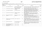
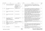
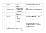
Chain Function
Item
Content
Default
Description
Access
by
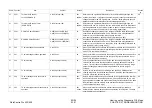
57
552**
Termination (Receive)
Level(G3M0:NCU0)
0 to 50(1step=-1dB)
43= -
43dBm
Determines the signal amplification level for a call terminating through the
outside line of NCU. If signals from the remote party cannot be detected at all,
change the data for 48 or a higher grade. However, noise will easily cause a
data error because the entire level of terminating signals rises.
CE
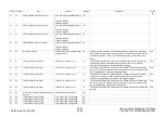
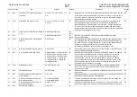
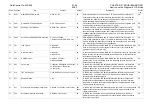
57
553**
Termination (Receive) Level
(G3M0:EXT0)
0 to 50(1step=-1dB)
43= -
43dBm
Determines the signal amplification level for a call terminating through the
extension line of NCU. If signals from the remote party cannot be detected at
all, change the data for 40 or a lower grade. However, noise will easily cause
a data error because the entire level of terminating signals rises.
CE
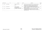
57
554**
G3M0 TX Cable Equalizer
0:0dB(0km) 1:4dB(2.7km)
2:8dB(5.3km) 3:12dB(8km)
01
Equalizes oscillation according to the length of unloaded cable between the
subscriber’s switchboard and main unit. When there are many fallbacks or
data errors in the overall transmission, change the value.
Individually reflectable on each speed dial (refer to page 2-207)
CE
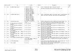
57
555**
G3M0 RX Cable Equalizer
0:0dB(0km) 1:4dB(2.7km)
2:8dB(5.3km) 3:12dB(8km)
01
Equalizes oscillation according to the length of unloaded cable between the
subscriber’s switchboard and main unit. When there are many fallbacks or
data errors in the overall receive, change the value. Individually reflectable on
each speed dial (refer to page 2-207)
CE
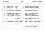
57
560
T1 timer setting at send operation
0 to 255 sec.
36
When the terminal is connected to fax operation, this data sets up time before
identifying the remote terminal. When the signal is properly detected or over
time occurs, the value will be reset.
CE
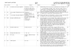
57
561
T1 timer setting at receive operation
0 to 255 sec.
39
When the terminal is connected to fax operation, this data sets up time before
identifying the remote terminal. When the signal is properly detected or over
time occurs, the value will be reset.
CE
57
562
T2 timer setting
0 to 255(1step=100ms)
60
timer is to detect the loss of an instruction and synchronized response. The
value will be reset when the flag sequence is properly detected or overtime
occurs. Try to increase the data when carrier is detected on receiving image
data or exchanging messages after image data which results in signal
collision.
CE
57
563
T3 timer setting
0 to 255(1step=100ms)
150=
15sec
Sets up time to call operator for warning when sending a message after
sending image data with delayed conversation. When the operator answers or
over time occurs, the data will be reset.
CE
57
564
T4 timer setting at auto send/receive
operation
0 to 255(1step=100ms)
30=
3sec
Sets up intervals between resend operations for all signals when the terminal
is connected for auto receive fax operation. Change the data to 35, 40, or 45
when signals are collided with each other by delayed transmission at the 4800
BPS(overseas) or at the network in the business environments where the
voice compression rate is high.)
CE
57
565
T4 timer setting at manual send/receive
operation
0 to 255(1step=100ms)
45=
4.5sec
When the terminal is connected to manual receive operation, this data
determines the intervals between resend operations for all signals. The data
should basically not be changed.
CE
Summary of Contents for WorkCentre Pro 423
Page 2: ......
Page 3: ...WorkCentre Pro 423 428 6HUYLFH 0DQXDO...
Page 6: ......
Page 8: ......
Page 9: ...INTRODUCTION...
Page 10: ......
Page 24: ...WorkCentre 423 428 03 02 INTRODUCTION 14 7 Translation of Warnings...
Page 25: ...CHAPTER 1 SERVICE CALL PROCEDURE...
Page 26: ......
Page 28: ...WorkCentre Pro 423 428 1 2 CHAPTER 1 SERVICE CALL PROCEDURE 03 02 1 1 Trimming...
Page 31: ...CHAPTER 2 TROUBLESHOOTING...
Page 32: ......
Page 76: ...WorkCentre Pro 423 428 2 44 CHAPTER 2 TROUBLESHOOTING 03 02 2 3 Level 2 Troubleshooting...
Page 243: ...CHAPTER 3 IMAGE QUALITY TROUBLESHOOTING...
Page 244: ......
Page 273: ...CHAPTER 4 DISASSEMBLY ASSEMBLY AND ADJUSTMENT...
Page 274: ......
Page 329: ...CHAPTER 5 PARTS LIST...
Page 330: ......
Page 415: ...03 02 5 2 Parts List WorkCentre Pro 423 428 5 85 CHAPTER 5 PARTS LIST...
Page 416: ...CHAPTER 6 GENERAL...
Page 417: ......
Page 456: ...CHAPTER 7 ELECTRICAL WIRING DIAGRAMS...
Page 457: ......
Page 476: ...CHAPTER 8 ACCESSORIES...
Page 477: ......
Page 535: ...WorkCentre Pro 423 428 8 58 CHAPTER 8 ACCESSORIES 03 02 8 22 Stamp Kit Red...
Page 536: ...CHAPTER 9 BSD Block Schematic Diagram...
Page 537: ......
Page 541: ......
Page 542: ......
Page 543: ......
Page 544: ......
Page 545: ......
Page 546: ......
Page 547: ......
Page 548: ......
Page 549: ......
Page 550: ......
Page 551: ......
Page 552: ......
Page 553: ......
Page 554: ......
Page 555: ......
Page 556: ......
Page 557: ......
Page 558: ......
Page 559: ......
Page 560: ......
Page 561: ......
Page 562: ......
Page 563: ......
Page 564: ......
Page 565: ......
Page 566: ......
Page 567: ......
Page 568: ......
Page 569: ......
Page 570: ......
Page 571: ......
Page 572: ......
Page 573: ......
Page 574: ......
Page 575: ......
Page 576: ......
Page 577: ......
Page 578: ......
Page 579: ......
Page 580: ......
Page 581: ......
Page 582: ......
Page 583: ......
Page 584: ......
Page 585: ......
Page 586: ......
Page 587: ......
Page 588: ......
Page 589: ......
Page 590: ......
Page 591: ......
Page 592: ......
Page 593: ......
Page 594: ......
Page 595: ......
Page 596: ......
Page 597: ......
Page 598: ......
Page 599: ......
Page 600: ......
Page 601: ......
Page 602: ......
Page 603: ......
Page 604: ......
Page 605: ......
Page 606: ......
Page 607: ......
Page 608: ......
Page 609: ......
Page 610: ......
Page 611: ......
Page 612: ......
Page 613: ......
Page 614: ......
Page 615: ......
Page 616: ......
Page 617: ......
Page 618: ......
Page 619: ......

