


03/02
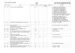
How to use the Diagnostic C/E Mode
WorkCentre Pro 423/428
2-187
CHAPTER 2 TROUBLESHOOTING
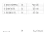
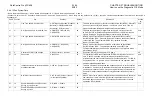
Chain Function
Item
Content
Default
Description
Access
by
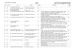
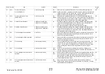
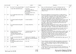
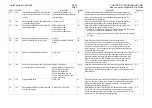
57
81
CNG Signal Send Start Time
Time from the end of dialing until the
first CNG signal is sent: 0 to
25500(ms) 1step=100ms
30
This data prescribes the time from the end of dialing until the first CNG signal
is sent in auto origination. Change the numeric value if a telephone
connection is automatically set up for a receiving terminal with a FAX/TEL auto
switching function due to the relationship of timing between termination and
CNG signal send.
CE
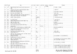
57
82
CNG Send Time.
0 to 255 sec.
58
The data specifies the period of time when the CNG signal is sent out by auto
send.
CE
57
85
CNG signal transmission timing by
manual send
0 to 25500ms (1step=100ms)
00
The data specifies the interval between pressing of the Start button and the
transmission of the CNG signal by the manual send. In case failure occurs at
the terminal when the CNG signal is sent immediately after pressing the Start
button, change the value.
CE
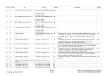
57
90
Disabling the keypad
0:enabled 1:disabled
00
The data is to meet the customer’s needs to perform the send operation only
by using the numbers stored in the speed dial and no dialing using the keypad
will be made.
CE
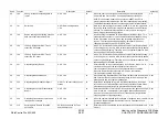
57
91
DTMF Idle Monitor Timer.
0 to 255 sec.
45
Sets up time to monitor when no transmission is made at the DTMF process
such as DTMF type relay send. The smaller the value, the more severe the
DTMF signal transmission at the send side. The greater the value, the easier
the operation at the emitting side of the DTMF signal, but there could be wrong
operation occurring resulting in longer monitor time required.
CE
57
92
DTMF Response Monitor Timer.
0 to 255 sec.
04
This timer monitors a response signal at the DTMF process such as DTMF
relay send.
CE
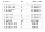
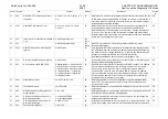
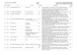
57
150
Line Power Feed Monitor.
0:Not monitored 1:Monitored
00
Specifies if the feeding status of current on the ISDN line will be monitored.
CE
57
151*
Line type (G4M0)
1:ISDN-CSDN 2:ISDN-PSDN
3:CSDN 4:PSDN
01
Sets up the line type when various ISDN and digital lines are supported. The
data needs not be changed as only ISDN-CSDN is supported currently.
CE
57
152
Default G4 Line Selection from ISDN-G4
and CSDN-G4 (X21)
0:ISDN-CSDN 1:CSDN(X21)
00
The data specifies priority of selection between the ISDN line and CSDN line
(high speed digital line) by G4 send. The data needs not be changed with G4
model which is not compatible with the CSDN line.
CE
57
153
Default G4-Network Protocol
0:X25PLP 1:T70NL 2:IS8208
02
The data specifies the initial setup of G4 protocol to be used for G4 send. The
data needs not be changed with the domestic machines connected to
INS64/1500(via DPBX). “T70NL” needs to be set up with G4 models
compatible to CSDN lines, only when the CSDN line has the priority.
CE
57
154
Default G4-Network Protocol on calling
ISDN-G4 (X21)
0:X25PLP 1:T70NL 2:IS8280
01
No change because X21 is not supported
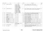
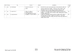
57
160
Restrictions on sending ISDN0 (network
guard)
0: Send not restricted 1:Send
restricted
00
The data can be changed when all send operations to the ISDN line via B1ch
need to be restricted. By changing the data, B1ch can be open to be used
only as a receive channel.
CE
57
161
Restrictions on sending ISDN1 (network
guard)
0: Send not restricted 1:Send
restricted
00
The data can be changed when all send operations to the ISDN line via B2ch
need to be restricted. By changing the data, B2ch can be open to be used
only as a receive channel.
CE
Summary of Contents for WorkCentre Pro 423
Page 2: ......
Page 3: ...WorkCentre Pro 423 428 6HUYLFH 0DQXDO...
Page 6: ......
Page 8: ......
Page 9: ...INTRODUCTION...
Page 10: ......
Page 24: ...WorkCentre 423 428 03 02 INTRODUCTION 14 7 Translation of Warnings...
Page 25: ...CHAPTER 1 SERVICE CALL PROCEDURE...
Page 26: ......
Page 28: ...WorkCentre Pro 423 428 1 2 CHAPTER 1 SERVICE CALL PROCEDURE 03 02 1 1 Trimming...
Page 31: ...CHAPTER 2 TROUBLESHOOTING...
Page 32: ......
Page 76: ...WorkCentre Pro 423 428 2 44 CHAPTER 2 TROUBLESHOOTING 03 02 2 3 Level 2 Troubleshooting...
Page 243: ...CHAPTER 3 IMAGE QUALITY TROUBLESHOOTING...
Page 244: ......
Page 273: ...CHAPTER 4 DISASSEMBLY ASSEMBLY AND ADJUSTMENT...
Page 274: ......
Page 329: ...CHAPTER 5 PARTS LIST...
Page 330: ......
Page 415: ...03 02 5 2 Parts List WorkCentre Pro 423 428 5 85 CHAPTER 5 PARTS LIST...
Page 416: ...CHAPTER 6 GENERAL...
Page 417: ......
Page 456: ...CHAPTER 7 ELECTRICAL WIRING DIAGRAMS...
Page 457: ......
Page 476: ...CHAPTER 8 ACCESSORIES...
Page 477: ......
Page 535: ...WorkCentre Pro 423 428 8 58 CHAPTER 8 ACCESSORIES 03 02 8 22 Stamp Kit Red...
Page 536: ...CHAPTER 9 BSD Block Schematic Diagram...
Page 537: ......
Page 541: ......
Page 542: ......
Page 543: ......
Page 544: ......
Page 545: ......
Page 546: ......
Page 547: ......
Page 548: ......
Page 549: ......
Page 550: ......
Page 551: ......
Page 552: ......
Page 553: ......
Page 554: ......
Page 555: ......
Page 556: ......
Page 557: ......
Page 558: ......
Page 559: ......
Page 560: ......
Page 561: ......
Page 562: ......
Page 563: ......
Page 564: ......
Page 565: ......
Page 566: ......
Page 567: ......
Page 568: ......
Page 569: ......
Page 570: ......
Page 571: ......
Page 572: ......
Page 573: ......
Page 574: ......
Page 575: ......
Page 576: ......
Page 577: ......
Page 578: ......
Page 579: ......
Page 580: ......
Page 581: ......
Page 582: ......
Page 583: ......
Page 584: ......
Page 585: ......
Page 586: ......
Page 587: ......
Page 588: ......
Page 589: ......
Page 590: ......
Page 591: ......
Page 592: ......
Page 593: ......
Page 594: ......
Page 595: ......
Page 596: ......
Page 597: ......
Page 598: ......
Page 599: ......
Page 600: ......
Page 601: ......
Page 602: ......
Page 603: ......
Page 604: ......
Page 605: ......
Page 606: ......
Page 607: ......
Page 608: ......
Page 609: ......
Page 610: ......
Page 611: ......
Page 612: ......
Page 613: ......
Page 614: ......
Page 615: ......
Page 616: ......
Page 617: ......
Page 618: ......
Page 619: ......