G E T T I N G S T A R T E D
1-7
STRIP MEASUREMENT TECHNIQUES
All control strip types should have at least a 30.5mm (1.25
”
) leader before the
first measurable patch. However, strips with less than a 30.5mm leader can
also be measured reliably if required. Refer to your Control Strip and
Balance Print Format Guide for leaderless strip measurement procedure.
Supported strip definitions and strip insertion direction information is
available in your Control Strip and Balance Print Format Guide shipped with
your instrument.
Strip Information
•
If a strip becomes “jammed” in your instrument during a measurement,
simultaneously press keys
llI
and
llll
labeled “MENU.” This should
cause the instrument to feed-out the strip. If this method does not work,
slowly pull strip out from the front of the instrument.
•
A strips is inserted into the instrument until it rests against the drive
rollers.
•
After a strip is initially inserted into the instrument, a one second delay
occurs before the drive mechanism is activated to allow time for proper
alignment.
•
Due to the amount of variation in printer balance strips, no guide setting
numbers appear in the display in the printer balance categories.
•
Due to the configuration of the instrument drive mechanism, 16mm wide
film control strips cannot be measured.
•
The instrument does measure strips that are creased.
Paper Strip
When a particular paper strip is selected, one or both of the displayed paper
guide setting numbers flash. If only one guide setting number is flashing, this
indicates the guide that the strip rests on first when measuring. In most cases
this only occurs on a strip that required multiple passes such as, Fuji CP-21.
Both guide setting numbers flash on single pass strips.
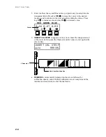
READ k:RA–4 ALL
AT
<
18
18
>
other
READ f:CP—21 CYN
AT
<
17
26
>
other
Indicates strip type
Indicates ALL patches are
read on one pass
Both guide setting number
flash, indicating a single
pass strip
Indicates CYN patches are
read one the first pass
Indicates strip type
One guide setting number
flashes, indicating strip
placement on this guide first
Multi
Pass
Single
Pass
Summary of Contents for 891
Page 1: ...891 892 A U T O M A T I C S T R I P R E A D I N G D E N S I T O M E T E R S Operation Manual...
Page 2: ......
Page 4: ......
Page 10: ...I N T R O D U C T I O N vi...
Page 34: ...S E C T I O N T H R E E 3 8...
Page 46: ...S E C T I O N F O U R 4 12...
Page 52: ...S E C T I O N F I V E 5 6...
Page 58: ...S E C T I O N S I X 6 6...
Page 60: ...S E C T I O N S E V E N 7 2...
Page 66: ...S E C T I O N E I G H T 8 6...
Page 68: ...A P P E N D I X A A 2...
Page 73: ...D 1 A P P E N D I X D Parts List and Packaging Drawings Parts List...
Page 74: ...A P P E N D I X D D 2 Packaging Drawing...
Page 78: ...A P P E N D I X E E 4...
Page 79: ......


