22
▸
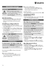
Place the quick-clamping nut
[8]
onto the spindle
[12]
.
▸
Tighten the clip of the quick-clamping nut
[8]
ma-
nually in the clockwise direction and fold down.
Loosening the quick-clamping nut
▸
Lock the spindle.
▸
Fold up the clip of the quick-clamping nut
[8]
.
▸
Manually unscrew the quick-clamping nut
[8]
in
an anti-clockwise direction.
If the quick-clamping nut is too tight, it can be
loosened using the two-hole wrench
[6]
.
Operation
Switching ON/OFF
WARNING !
Risk of severe injuries.
¾
Always guide the machine with both
hands.
¾
First switch on, then bring the
attachment into contact with the
workpiece.
WARNING !
Danger of unintentional starting
¾
Always switch off the machine when
the mains plug is removed from the
plug socket or if a power failure has
occurred.
DANGER!
Risk of a dust explosion.
¾
Take care to prevent the machine
from drawing in additional dust and
chips.
¾
Keep away from dust deposits when
switching the machine ON and OFF.
WARNING !
Risk of severe injuries.
Â
If the machine is set to continuous run-
ning, it will continue to run if it is torn
out of your hand.
¾
Always hold the machine with both
hands at the handles provided, take
up a stable posture and concentrate
on the work in hand.
CAUTION!
Risk of severe injuries
¾
For safety reasons, always use the
safety guard when working with
cutting wheels.
Two-hole nut
Tightening the two-hole nut (Fig. III)
Attention!
The two sides of the two-hole nut
[7]
are different.
Screw the two-hole nut
[7]
onto the spindle as
follows:
With thin grinding wheels
•
The collar of the two-hole nut
[7]
faces upwards
so that the thin grinding wheel can be securely
clamped.
With thick grinding wheels
•
The collar of the two-hole nut
[7]
faces down-
wards so that the two-hole nut can be securely
screwed onto the spindle.
▸
Lock the spindle.
▸
Tighten the two-hole nut in clockwise direction
using the two-hole wrench
[6]
.
Loosening the two-hole nut
▸
Lock the spindle.
▸
Unscrew the two-hole nut
[7]
in an anti-clockwise
direction using the two-hole wrench
[6]
.
Quick-clamping nut
Tightening the quick-clamping nut
Attention!
Use the quick-clamping nut
[8]
only on machines
with the “quick-clamping system”.
Attention!
If the abrasive wheel
[9]
is thicker than 6 mm in
the clamping area, the quick-clamping nut must not
be used!
¾
Use the two-hole nut
[7]
with the two-hole
wrench
[6]
.
▸
Lock the spindle.
▸
Fold up the clip of the quick-clamping nut
[8]
.
Summary of Contents for FKWS 9-125
Page 3: ...3 I 12 13 6 2 1 4 3 7 9 8 10 11 5...
Page 4: ...12 B A C 4 III II 14 3...
Page 111: ...111 GR Adolf W rth GmbH Co KG 3 1...
Page 112: ...112 a b c d e f g...
Page 113: ...113 h i j k l m n o p a...
Page 114: ...114 b c d e f g h i j k a b...
Page 115: ...115 c d e f a a b...
Page 116: ...116 FI FI P2 FI 30 mA...
Page 118: ...118 I II 1 2 3 4 5 6 7 8 9 10 11 12 13 14 2 II 3 4 mm 14 3 3 13...
Page 119: ...119 8 9 6 mm 7 6 8 8 12 8 8 8 6 III 11 3 9 11 III 7 7 7 7 6 7 6...
Page 120: ...120 1 1 30 40 W rth...
Page 193: ...193 BG Adolf W rth GmbH Co KG 3 1...
Page 194: ...194 a b c d e f g...
Page 195: ...195 h i j k l m n o p...
Page 196: ...196 a b c d e f g h i j a b...
Page 197: ...197 c d e f a a b...
Page 198: ...198 FI FI P2 30 mA...
Page 200: ...200 1 2 3 4 5 6 7 8 9 10 11 12 13 14 2 3 4 mm 14 3 3 13...
Page 201: ...201 8 9 6 mm 7 6 8 8 12 8 8 8 6 11 3 9 11 7 7 7 7 6 7 6...
Page 202: ...202 1 1 30 40 W rth...
Page 234: ...234 RU Adolf W rth GmbH Co KG 3 1...
Page 235: ...235 a b c d e f g...
Page 236: ...236 h i j k l m n o p a...
Page 237: ...237 b c d e f g h i j k a b c...
Page 238: ...238 d e f a a b...
Page 239: ...239 FI P2 30 A...
Page 241: ...241 I II 1 2 3 4 5 6 7 8 9 10 11 12 13 14 2 II 3 4 14 3 3...
Page 242: ...242 III 7 7 7 7 6 7 6 8 9 6 7 6 8 13 III 11 3 9 11...
Page 243: ...243 8 12 8 8 8 6 1 1 30 40...
Page 244: ...244 W rth 1 W rth masterService http www wuerth com partsmanager W rth...


