21
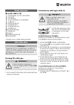
Device elements
Overview (Fig. I/III)
1
Trigger switch for switching ON/OFF
2
Auxiliary handle
3
Safety hood
4
Rubber plate with abrasive sheet*
6
Cup brush*
6
Two-hole wrench*
7
Two-hole nut*
8
Quick clamping nut
9
Abrasive wheel or disc*
10
Safety guard
*
11
Supporting flange
12
Spindle
13
Spindle locking knob
14
Locking lever
*
Accessory,
not
included in the scope of delivery
Start-up
Attention!
Before initial use, check that the specifications of
your mains power supply correspond to the mains
voltage and mains frequency indicated on the
name plate.
Attaching auxiliary handle
CAUTION!
Risk of severe injuries.
¾
Work only with the auxiliary handle
[2]
attached!
▸
Screw in the auxiliary handle firmly on the left-
hand or right-hand side of the machine.
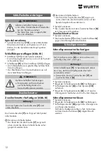
Attaching the safety hood (Fig. II)
CAUTION!
Risk of severe injuries.
¾
For safety reasons, use only the safety
hood intended for the respective
grinding wheel!
Use only attachments with a
clearance of at least 3.4 mm to
the safety hood.
Safety hood for grinding
Intended for use in work with roughing discs, multi-
disc grinding wheels, diamond cut-off wheels.
▸
Press and hold locking lever
[14]
.
▸
Push safety hood
[3]
onto the spindle neck as
shown.
▸
Adjust the position of the safety hood to the posi-
tion of the hand on the machine. Turn the safety
hood until it is in the desired position.
3
The closed side of the safety hood must be facing
towards the operator.
▸
Release the locking lever and turn the safety hood
until the locking lever audibly engages.
▸
Check that the dust extraction hood is secure: The
lever must be engaged and it must not be possible
to turn the safety hood.
Safety guard for cut-off grinding
Intended for use with cut-off wheels, diamond cut-off
wheels.
▸
Attach as described above in “Safety hood for
grinding”.
Attaching grinding wheel
WARNING !
Risk of severe injuries.
¾
Pull the mains plug out of the plug
socket before all tooling operations.
¾
The machine must be switched off
and at a standstill.
Locking spindle
▸
Only press in the spindle locking knob
[13]
when the device is stationary and turn the spindle
manually until the spindle locking knob audibly
engages.
Fitting abrasive wheel or disc (Fig. III)
▸
Push supporting flange
[11]
onto the spindle.
3
It is fitted correctly when it cannot be turned on
the spindle.
▸
Push abrasive wheel
[9]
onto the supporting
flange
[11]
.
•
The grinding wheel must rest uniformly on the
supporting flange.
• The metal flange of cut-off wheels must rest on the
supporting flange.
Summary of Contents for FKWS 9-125
Page 3: ...3 I 12 13 6 2 1 4 3 7 9 8 10 11 5...
Page 4: ...12 B A C 4 III II 14 3...
Page 111: ...111 GR Adolf W rth GmbH Co KG 3 1...
Page 112: ...112 a b c d e f g...
Page 113: ...113 h i j k l m n o p a...
Page 114: ...114 b c d e f g h i j k a b...
Page 115: ...115 c d e f a a b...
Page 116: ...116 FI FI P2 FI 30 mA...
Page 118: ...118 I II 1 2 3 4 5 6 7 8 9 10 11 12 13 14 2 II 3 4 mm 14 3 3 13...
Page 119: ...119 8 9 6 mm 7 6 8 8 12 8 8 8 6 III 11 3 9 11 III 7 7 7 7 6 7 6...
Page 120: ...120 1 1 30 40 W rth...
Page 193: ...193 BG Adolf W rth GmbH Co KG 3 1...
Page 194: ...194 a b c d e f g...
Page 195: ...195 h i j k l m n o p...
Page 196: ...196 a b c d e f g h i j a b...
Page 197: ...197 c d e f a a b...
Page 198: ...198 FI FI P2 30 mA...
Page 200: ...200 1 2 3 4 5 6 7 8 9 10 11 12 13 14 2 3 4 mm 14 3 3 13...
Page 201: ...201 8 9 6 mm 7 6 8 8 12 8 8 8 6 11 3 9 11 7 7 7 7 6 7 6...
Page 202: ...202 1 1 30 40 W rth...
Page 234: ...234 RU Adolf W rth GmbH Co KG 3 1...
Page 235: ...235 a b c d e f g...
Page 236: ...236 h i j k l m n o p a...
Page 237: ...237 b c d e f g h i j k a b c...
Page 238: ...238 d e f a a b...
Page 239: ...239 FI P2 30 A...
Page 241: ...241 I II 1 2 3 4 5 6 7 8 9 10 11 12 13 14 2 II 3 4 14 3 3...
Page 242: ...242 III 7 7 7 7 6 7 6 8 9 6 7 6 8 13 III 11 3 9 11...
Page 243: ...243 8 12 8 8 8 6 1 1 30 40...
Page 244: ...244 W rth 1 W rth masterService http www wuerth com partsmanager W rth...


