WIRTGEN HAMM GRW 280 Operating Manual Download Page 37

 General

 Stickers on the machine

© HAMM AG 2011

2153734_02_BAL_GRW280_H195_en

37

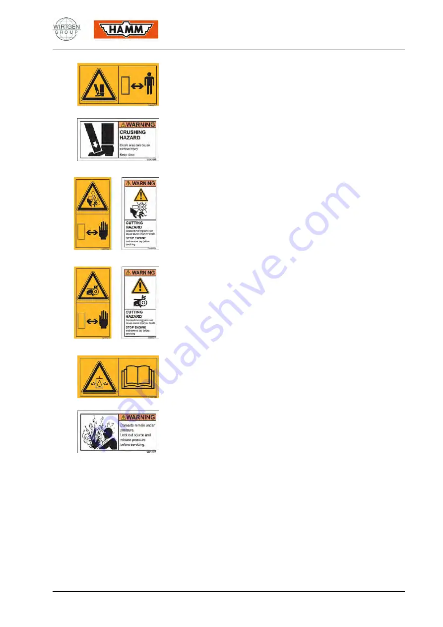
Edge pressing assembly

Risk of crushing! Pinch point can cause serious injuries or fatality. Keep

away. Prior to maintenance and adjustment works, shut down machine

and remove ignition key.

Fan blade

Hazard due to rotating parts! With the machine running, serious injuries

or fatality may be caused. Prior to maintenance work, shut down engine

and remove ignition key. Wait until all machine components have come

to a standstill.

V-belt

Risk of trapping! Open belts or chains. With the machine running,

serious injuries or fatality may be caused. Prior to maintenance work,

shut down engine and remove ignition key. Wait until all machine

components have come to a standstill.

Accumulator

Tank under pressure. System contains accumulator. Prior to starting

service work, read operating and service manual.

Summary of Contents for HAMM GRW 280

Page 1: ...GRW 280 OPERATING MANUAL HAMM AG 2011 Version 02 H195 Series 0012 valid from Serial No 01 03 2010 Date of first issue 2153734 Order number en Language...

Page 2: ..._en Original operating manual Date of first issue 01 03 2010 Date of change 01 07 2011 Copyright HAMM AG 2011 The disclosure as well as the duplication of this document the use and the forwarding of i...

Page 3: ...HAMM AG 2011 2153734_02_BAL_GRW280_H195_en 3 This operating manual is valid for the following roller types RUBBER WHEELED ROLLER GRW 280 10 GRW 280 12 GRW 280 16 GRW 280 20 GRW 280 24 GRW 280 28...

Page 4: ...02 Use 14 1 02 01 Intended use 14 1 02 02 Reasonably forseeable misuse 15 1 02 03 Residual risks 15 1 02 04 Climatic conditions 16 1 03 Environmental protection 17 1 04 Disposal 17 1 05 EC confirmity...

Page 5: ...61 2 02 General view of instruments and operating elements 64 2 02 02 Control stand 64 2 02 04 Drive unit diesel engine 71 2 02 08 Drive 72 3 Operation 73 3 00 Instruments and operating elements 73 3...

Page 6: ...and adding ballast 137 4 Maintenance 140 4 00 General maintenance instructions 140 4 00 01 Operation monitoring 140 4 00 02 Maintenance overview 141 4 00 03 Running in regulations 144 4 00 04 Require...

Page 7: ...ng filling level hydraulic oil 169 4 05 03 Changing hydraulic oil and ventilation filter 170 4 05 04 Replacing filter insert of pressure filter for hydraulic system 171 4 08 Drive 172 4 08 01 General...

Page 8: ...roup Lubricants 191 5 00 04 Coolant conditioning 194 5 00 05 Fuel 195 5 00 06 Starting torques 196 5 01 Technical data 197 5 01 01 GRW 280 10 197 5 01 02 GRW 280 12 199 5 01 03 GRW 280 16 201 5 01 04...

Page 9: ...e e g accident prevention regulations Maintenance and care of the diesel engine have to be performed according to these motor instructions Any safety notes have to be followed 609 08 1 00 02 Product i...

Page 10: ...ions downtimes and resulting damage 609 09 1 00 05 Packaging and storage We have carefully packed our products to ensure proper protection in transit Please check both packaging and the goods yourselv...

Page 11: ...single figure The positions marked with numbers apply to operating elements control units and switches They are identical to the numbers in the section Overview of Instruments and Operating Elements...

Page 12: ...al injuries 001 01 WARNING Refers to situations that may be dangerous If this situation is not avoided fatality or very serious injuries may be caused 002 01 CAUTION Refers to situations that may be d...

Page 13: ...diesel engine If necessary additional information The entire operating manual must always be available at the machine and be accessible to the authorized operating personnel at all times Prior to oper...

Page 14: ...bedding pavement or similar ramable subgrade in layers The machine may only be deployed on surfaces that can support it Subgrade not capable of bearing is e g high fillings batters roadside ditches T...

Page 15: ...with high pressure cleaners or fire extinguishing equipment Towing trailing loads Non compliance with maintenance intervals Omission of measurements and tests to detect damages early Omission of repla...

Page 16: ...rating area e g with Improper operation Reduction in performance and or the machine s functionality may occur at the machine with Improper operation Improper maintenance and or repair works Improper o...

Page 17: ...e is one of our major tasks Properly disposed devices avoid negative impacts on human beings and the environment and allows re using our precious resources Operating supply items Please dispose all op...

Page 18: ...arately by HAMM and will be submitted to you togehter with the machine The pictogram represents the machine s conformity with relevant EU Directives The CE mark of the machine is part of the type plat...

Page 19: ...machine frame see page 46 A Description B Homologation C Type D Year of construction E Chassis number F Engine power G Admissible total weight only valid for public roads H Admissible axle load front...

Page 20: ...f the machine was measured according to the EC Sound Emission Directive in the version 2000 14 EC The sound and vibration indications on the driver s seat are in line with the requirements of the EC M...

Page 21: ...ation The weighted rms values of the acceleration with whole body vibrations on the operator s seat have been accessed in accordance with EN1032 and do not exceed aw 0 5 m s Hand arm vibrations The we...

Page 22: ...ding to the rules of action in the case of perturbation Please adhere to the following instructions Please drive the machine only if you are entirely familiarised with the operating and control elemen...

Page 23: ...permitted by the StVZO Germany and must be removed when travelling on public roads Additional information In case you should obtain additional technical and or safety relevant information they also m...

Page 24: ...sel engine switched off an area 1 metre around the machine is defined as danger zone Only authorised operating personnel is allowed to enter the danger zone Zone moving For a moving machine the danger...

Page 25: ...ns When loading please observe the following instructions Adhere to section Transport as specified in the safety instructions Observe weight and dimensions see page 197 sqq Observe the legally require...

Page 26: ...er Do not overload the lashing points with a tensioning device see the loading tables To increase load safety use additional precautions for securing the load including e g wheel stop wedges or a posi...

Page 27: ...machine weight 10000 kg Maximum permissible ramp slope 17 5 10 with substructure ballast UB 28 5 16 without substructure ballast UB Chain lashing device Nominal chain size quality class and LC in daN...

Page 28: ...machine weight 12600 kg Maximum permissible ramp slope 17 5 10 with substructure ballast UB 28 5 16 without substructure ballast UB Chain lashing device Nominal chain size quality class and LC in daN...

Page 29: ...machine weight 15500 kg Maximum permissible ramp slope 17 5 10 with substructure ballast UB 28 5 16 without substructure ballast UB Chain lashing device Nominal chain size quality class and LC in daN...

Page 30: ...machine weight 16000 kg Maximum permissible ramp slope 17 5 10 with substructure ballast UB 28 5 16 without substructure ballast UB Chain lashing device Nominal chain size quality class and LC in daN...

Page 31: ...machine weight 20600 kg Maximum permissible ramp slope 17 5 10 with substructure ballast UB 28 5 16 without substructure ballast UB Chain lashing device Nominal chain size quality class and LC in daN...

Page 32: ...machine weight 24000 kg Maximum permissible ramp slope 17 5 10 with substructure ballast UB 28 5 16 without substructure ballast UB Chain lashing device Nominal chain size quality class and LC in daN...

Page 33: ...machine weight 28500 kg Maximum permissible ramp slope 17 5 10 with substructure ballast UB 28 5 16 without substructure ballast UB Chain lashing device Nominal chain size quality class and LC in daN...

Page 34: ...unless the current machine weight is already known Otherwise use the maximum weight see type plate as the machine weight 000 16 Select the corresponding loading table based on the machine weight If t...

Page 35: ...can cause serious injuries or fatality Seat belt obligatory only with ROPS cabin or ROPS roll over bar Risk of being thrown out of tipping machine can cause serious injuries or fatality Put on safety...

Page 36: ...machine components have come to a standstill Hot surface Risk of burns Surfaces can be very hot Do not touch surface Keep away Air conditioning Risk of burns Coolant of the air conditioning can cause...

Page 37: ...ous injuries or fatality may be caused Prior to maintenance work shut down engine and remove ignition key Wait until all machine components have come to a standstill V belt Risk of trapping Open belts...

Page 38: ...vements can cause serious injuries or fatality Keep away Danger of overturning Pay attention that there is sufficient stability when working with rollers of small roller drum width Pay attention to pe...

Page 39: ...he battery isolating switch only with the enginge stopped Before you start with service works read the operating and maintenance instructions 12 V fuses Diesel Diesel tank Use diesel with a sulphur co...

Page 40: ...ith the machine or maintaining it First aid kit Panolin Biodegradable hydraulic oil in use 1 12 02 Information sign In the following you will find a list of all information signs Illustrations and val...

Page 41: ...the machine HAMM AG 2011 2153734_02_BAL_GRW280_H195_en 41 Sprinkling Water tank filling Water tank outlet Additive sprinkling Water tank inlet of additive sprinkling Water tank outlet of additive spr...

Page 42: ...machine 42 2153734_02_BAL_GRW280_H195_en HAMM AG 2011 Hydraulic oil filling level Hydraulic oil reservoir inlet Hydraulic oil reservoir outlet Socket 12V Engine oil outlet Water sump fuel filter outle...

Page 43: ...the machine HAMM AG 2011 2153734_02_BAL_GRW280_H195_en 43 Coolant inlet Inflation pressure Tyre without water filling Inflation pressure Tyre with water filling Guaranteed sound power level Expert in...

Page 44: ...General Stickers on the machine 44 2153734_02_BAL_GRW280_H195_en HAMM AG 2011 Maintenance overview...

Page 45: ...arge steering angle to both sides Level compensation upwards and downwards Service brake During operation the machine is braked with the hydrostatic drive multiple disc spring operated brake Wear free...

Page 46: ...is possible that these instructions include descriptions of operating elements not installed on your machine 000 03 2 01 01 Chassis safety devices A Stickers indicating dangers B Towing loop for crane...

Page 47: ...teering column E Stacker for operating manual first aid kit F Heating ventilation cooling G ROPS cabin type plate H cabin door J Position for fire extinguisher K Windshield washer liquid reservoir ROP...

Page 48: ...ngine A Diesel engine with drive units B Coolant inlet C Fuel tank D Fuel system E Fuel intake F Air filter G Turbo supercharger exhaust system H Oil inlet J Cooling system A Coolant compensator tank...

Page 49: ...Description General view of machine HAMM AG 2011 2153734_02_BAL_GRW280_H195_en 49 A Oil outlet...

Page 50: ...ption General view of machine 50 2153734_02_BAL_GRW280_H195_en HAMM AG 2011 2 01 05 Hydraulic oil supply A Hydraulic oil reservoir B Oil inlet and oil dipstick with ventilation filter A Hydraulic oil...

Page 51: ...Description General view of machine HAMM AG 2011 2153734_02_BAL_GRW280_H195_en 51 A Oil outlet...

Page 52: ...ion General view of machine 52 2153734_02_BAL_GRW280_H195_en HAMM AG 2011 2 01 06 Electrical equipment Chassis A Battery isolating switch B Fuses C Battery A Battery isolating switch B Fuses C Fuse oc...

Page 53: ...2011 2153734_02_BAL_GRW280_H195_en 53 A Main fuses B Battery A Main fuses B Battery C Battery compartment screw connectionBattery compartment screw connection Battery compartment screw connection Eng...

Page 54: ...54 2153734_02_BAL_GRW280_H195_en HAMM AG 2011 2 01 08 Drive Drive A Brake drive B Gear drive C Smooth tyre oil outlet filling level control screw oil inlet Rear wheel A Oil outlet B Filling level cont...

Page 55: ...Description General view of machine HAMM AG 2011 2153734_02_BAL_GRW280_H195_en 55 Smooth tyre A Scraper B Smooth tyre C Tire filling system Front wheel A Valve B Tyre inflator hose...

Page 56: ...Description General view of machine 56 2153734_02_BAL_GRW280_H195_en HAMM AG 2011 2 01 09 Steering system A Steering cylinder B Bearing block oscillation arm C Tie rod A Steering cylinder C Tie rod...

Page 57: ...machine HAMM AG 2011 2153734_02_BAL_GRW280_H195_en 57 2 01 12 Water system A Sprinkler nozzles B Water inlet C Water tank D Water outlet E Water filter F Water pump A Sprinkler nozzles D Water outlet...

Page 58: ...Description General view of machine 58 2153734_02_BAL_GRW280_H195_en HAMM AG 2011 Additive sprinkling A Additive sprinkling water pump B Additive filter C Inlet additive tank...

Page 59: ...2153734_02_BAL_GRW280_H195_en 59 2 01 20 Tyre heating Tyre heating A Ignition unit B Infrared radiator group C Gas supply pipe Liquid gas bottles A Main stop valve B 11 step controller C Skid catch D...

Page 60: ...achine 60 2153734_02_BAL_GRW280_H195_en HAMM AG 2011 2 01 27 Edge pressing and cutting assembly KAG A Pressing disk B Pipe with sprinkler nozzle C Lubrication nipple D Hydraulic cylinder E Additional...

Page 61: ...hine HAMM AG 2011 2153734_02_BAL_GRW280_H195_en 61 2 01 40 Special equipment Accessory A Working spotlight B Loudspeaker C Rear view mirror D Radio CD E Tachograph F Safety belt G Second drive lever A...

Page 62: ...Description General view of machine 62 2153734_02_BAL_GRW280_H195_en HAMM AG 2011 A Tool box Comfort loading A Lashing point...

Page 63: ...Description General view of machine HAMM AG 2011 2153734_02_BAL_GRW280_H195_en 63 Thermal aprons A Thermal front aprons B Thermal rear aprons...

Page 64: ...nstruments and operating elements are marked by numbers You will find a description in chapter 3 under the corresponding element 000 04 2 02 02 Control stand Steering column 302 Switch EMERGENCY STOP...

Page 65: ...05 Warning flasher switch 307 Switch lighting 310 Switch electrical system engine start 311 Rotating light switch 322 Tyre heating 324 Preselection sprinkling 406 Cigarette lighter Socket 12 V Operato...

Page 66: ...Description General view of instruments and operating elements 66 2153734_02_BAL_GRW280_H195_en HAMM AG 2011 Operator s cabin rear wall 405 Socket 12 V ROPS area behind the seat 405 Socket 12 V...

Page 67: ...m cabin door A Handle B Actuation button Driver s seat 520 Seat adjustment weight height 521 Seat adjustment forward backward 522 Seat backrest adjustment 523 Seat adjustment elbow rest Driver s seat...

Page 68: ...8 2153734_02_BAL_GRW280_H195_en HAMM AG 2011 Control unit normal mode 101 Display system info 237 Pilot light fuel 301 Switch signal horn 353 Switch parking brake monitoring 375 Switch system info Con...

Page 69: ...Control unit sprinkling 207 Pilot light sprinkling 232 Pilot light sprinkling stage 238 Pilot light filling level sprinkling 317 Switch sprinkling 373 Switch sprinkling stage Operating unit tyre filli...

Page 70: ...arge current 202 Pilot light oil pressure 203 Pilot light air filter 204 Pilot light parking brake 206 Pilot light coolant level 214 Pilot light hydraulic oil filter 220 Pilot light STOP 227 Pilot lig...

Page 71: ...n General view of instruments and operating elements HAMM AG 2011 2153734_02_BAL_GRW280_H195_en 71 2 02 04 Drive unit diesel engine 356 Battery isolating switch 538 Steps 530 Manual pump parking brake...

Page 72: ...tion General view of instruments and operating elements 72 2153734_02_BAL_GRW280_H195_en HAMM AG 2011 2 02 08 Drive Tyre scraper brushes 536 Locking device scraper Tyre scraper PUR 536 Locking device...

Page 73: ...e switch 375 you can select the corresponding display Operating hours After the electrical system is switched on the operating hours of the machine are shown in the display field Maintenance work has...

Page 74: ...ithin the adjusted limit values display shows the actual value Temperature above the adjusted asphalt temperature display flashes between HI and the actual value in additon you hear an acoustic signal...

Page 75: ...ng of the colours Red Danger important reminder Yellow Warning notice malfunction Green Switch in check 000 06 201 Charge current Flashing during operation indicates missing charging current 201 06 20...

Page 76: ...ol unit 353 and or the EMERGENCY STOP switch 302 204 07 206 Coolant level Flashing during operation indicates that the coolant level in the cooling system of the diesel engine is not sufficient 206 02...

Page 77: ...tes a serious malfunction of the machine At the same time an acoustic signals sounds Further operation is inadmissible 1 Park the machine out of the danger zone 2 Shut down the diesel engine immediate...

Page 78: ...ling 232 02 234 Diesel engine Lighting up during operation indicates a malfunction of the diesel engine and or of the machine components 1 Stop machine 2 Call up the diagnostic code by the switch 375...

Page 79: ...ot light STOP 220 and the pilot light 239 have not gone out after ca 30 seconds after the diesel engine was started it is not allowed to run the machine 4 Park the machine out of the danger zone Furth...

Page 80: ...AMM AG 2011 245 Tyre heating The two pilot lights indicate the operating status of the tyre heaters front and rear infrared radiator groups Flickering tyre heating in the ignition phase Steady light t...

Page 81: ...MERGENCY STOP as operation brake 002 03 Pressing the switch Stops the hydraulic drive Switches off the diesel engine Activates the hydraulic brakes And the notice STOP is displayed in the indication 1...

Page 82: ...flashes Off position 0 305 02 307 Lighting When the electrical system is switched off switch 310 in 0 position and the switch is in position I only the parking lights are switched on When the electri...

Page 83: ...switched on for a longer period position I the battery discharges rapidly If the engine is started with the EMERGENCY STOP switch pressed the engine will not start for safety reasons To activate the m...

Page 84: ...7 05 322 Tyre heating Using the switch you can switch on and or off the tyre heating and activated deactived the gas supply On position I switch button lights up Off position 0 The two pilot lights 24...

Page 85: ...y pump of the windshield washer is switched on Only as long as the switch is pressed a moistening of the windscreen takes place Washing windscreen position I Off position 0 Washing rear pane position...

Page 86: ...ched off 004 03 The circuit to the minus terminal of the battery is interrupted at the battery isolation switch All electric components will be off Electrical circuit interupted position 0 key release...

Page 87: ...sition lock pilot light 204 flashes 000 22 361 Air conditioning temperature The cooling system is switched on with the switch The air flow is cooled down through the heat exchanger of the air conditio...

Page 88: ...S Reduce limit value by 1 C or 1 F PRESS Pressing the button longer you can increase reduce the value gradually in steps of 5 C or 5 F Function MODE Show adjusted maximum limit value PRESS MODE Symbol...

Page 89: ...lighter Cigarette lighter Press the cigarette lighter until it engages spiral wound filament is heated After a short time the lighter springs out and can be removed from the socket Socket 12 V Power...

Page 90: ...pre selected velocity range 314 If the machine is equipped with a back up alarm an acoustic signal sounds when travelling reverse 501 14 502 0 position lock parking brake For latching the right drive...

Page 91: ...UP Lower KAG DOWN The KAG is installed on the right hand side only and is operated using the switch at the right hand drive lever Additive sprinkling Additive sprinkling can be switched on and off at...

Page 92: ...weight by turning the lever to the left or right between 50 kg and 130 kg The adjusted weight is displayed in the adjacent window The seat height can be adjusted to several levels The seat latches to...

Page 93: ...the seat pedestal during driving Adjust the seat pedestal only on an even surface Use it for transporting only if the driver doors are closed and the seat is in central position of the cabin 002 05 T...

Page 94: ...t pedestal only on an even surface Use it for transporting only if the driver doors are closed and the seat is in central position of the cabin 002 05 NOTICE Damage to property on the operator platfor...

Page 95: ...into further rest positions to the left or the right Latched hand lever position 0 Unlatched hand lever position I Outer seat position NOTICE Damage to property on the operator platform Damage due to...

Page 96: ...xion lever B Locking is also possible in intermediate positions 534 01 536 Locking device of scraper Version Tyres brushes The scraper is fixed in a specified position or attached to the tyres by mean...

Page 97: ...n Open cabin door 1 Press handle A open cabin door and interlock with cabin Unlock cabin door 1 Pull actuation button B the locking system is open 537 00 538 Steps The steps to the control stand can a...

Page 98: ...chine 002 07 After working on electronic components associated with the control such as adjustable resistors potentiometers sensors switches etc or their replacement an electronic system setup must be...

Page 99: ...neck 701 15 Air 1 Check the air pressure in the tyres 701 16 Control stand WARNING Uncontrolled movements Risk of injury by uncontrolled movements when changing the seat pedestral position Operate the...

Page 100: ...e on the side of the cabin ROPS 002 24 Inadmissable seat position It is not admissable to operate the machine if parts protrude the steering console or the seat pedestal on the side of the cabin ROPS...

Page 101: ...ted by starting with an external power source see page 112 sqq 703 04 Start position before starting Set the operating elements to their start position prior to the start of the engine 1 Drive lever 5...

Page 102: ...the engine until driveaway Warm up the machine during the warming phase with moderate speed and low load until the oil in the hydraulic system has heated to approx 20 C 68 F 002 15 The acceleration an...

Page 103: ...lock parking brake 502 position I The parking brake has been released Pilot light 204 goes out 4 Drive lever 501 to the FRONT or to the REAR If the machine is equipped with a back up alarm an acousti...

Page 104: ...97 sqq When the drive lever 501 is pushed to the stop the driving speed is limited to the defined final speed After the start of the engine the velocity range 1 is active 708 08 Do not drive on slopes...

Page 105: ...ne even if you leave the operator platform only for short time 002 22 Stop 1 Drive lever 501 CENTRE 2 Service brake 512 PRESS pedal In exeptional cases the speed of the diesel engine may increase in t...

Page 106: ...000 02 Leaving the machine The driver may only leave the machine when orderly parked Traffic regulations have to be observed as well Before leaving the machine the driver must ensure that The driver s...

Page 107: ...e fault is displayed by further active pilot lights 1 Park the machine out of the danger zone and switch off the diesel engine 2 Rectify the cause immediately Warning notice malfunction A pilot light...

Page 108: ...quantity and pump pause time The water pump can also be switched manually to continuous operation at any time 726 29 Sprinkling The automatic sprinkling system is switched on and off with the switch...

Page 109: ...w lateral cap nut D from the sprinkler nozzles C and remove together with valve insert and membrane Reassemble spraying nozzle after emptying the nozzle casing 3 Unscrew filter head E at the water tan...

Page 110: ...ng The additive sprinkling is switched on and off using the switch 503 As long as the switch is pressed the tyres are sprinkled The frequency of sprinkling depends on the temperature of the tyres Cold...

Page 111: ...ts premature wear Rinse out dirt embedded between roller drums tyres with water jet Remove strongly adhesive dirt with spatula or similar tool 744 00 Applying the scraper 1 Switch off diesel engine an...

Page 112: ...he positive terminal of the charged battery plus sign 2 Connect the other terminal clamp of this lead to the positive terminal of the discharged battery plus sign 3 Connect one terminal clamp of the s...

Page 113: ...3734_02_BAL_GRW280_H195_en 113 Removing leads 1 To prevent overloads in the electrical system switch on an electrical component in the discharged vehicle e g driving light before removing the jump lea...

Page 114: ...L_GRW280_H195_en HAMM AG 2011 3 10 Towing General WARNING Brake out of order Risk of fatal injury due to unintentional rolling away of the machine Prior to releasing the brake secure the machine again...

Page 115: ...chains when salvaging the machine on an uphill slope brakes not released 717 09 Before towing 1 Drive lever 501 CENTRE 2 0 position lock 502 position 0 3 Shut down diesel engine if still functional 4...

Page 116: ...below 5 Remove towing bar 717 07 Separating the hydrostatic drive power train Only if the oil flow can circulate without pressure in the hydraulic system can the machine be towed For this perform the...

Page 117: ...the spring operated brakes by pumping at lever A approx 30 pump strokes 6 During towing the spring operated brakes must be kept open by constant and slow pumping due to interior leaks 719 18 Making pa...

Page 118: ...y adjusting the discs The direction is set by turning the disc ring For drying or de icing of the front or rear window the air flow must be directed to the windows Heating The heat exchanger for the h...

Page 119: ...ecure machine against rolling away with wedges or blocks WARNING Danger of falling Ensure that the stairs are locked prior to entering the maintenance point are locked into operating position when lea...

Page 120: ...Folding in step 1 Pull handle A upwards and pull bar B out of lockable opening C 2 Turn handle A into vertical position 3 Retract stairs into operating position and click into place and secure 4 Lock...

Page 121: ...s Check filling levels only when machine is cooled down 002 10 Prior to opening the engine hood 1 Switch off diesel engine and remove ignition key 2 Unfold stairs to maintenance point and lock safely...

Page 122: ...there are no persons within the hazardous area of the stand space A marked Take care of your feet when closing the engine hood The engine hood extends into the area where you stand Completely remove t...

Page 123: ...d This avoids asphalt sticking to the tyres Thermal aprons do not provide active heating They are used to form a space around the rubber tyres which is closed at its lateral and upper sides and allows...

Page 124: ...tyre heating is only required prior to the rolling procedure and when the layer material cools down 731 02 Arrangement and function The heating system consists of gas fired infrared radiators which ar...

Page 125: ...obtain a bottle bank Pursuant to the applicable regulations the bottle and controller arrangements are located outside the closed driver s cab Solenoid valves are used to switch the radiator groups ei...

Page 126: ...a recurrent inspection is performed as required by accident prevention regulations Secure every liquid glass bottle so as to prevent any unwanted change of position e g falling over or drop Ensure suf...

Page 127: ...NG Cold burn Icing may occur at the surface of a liquid gas bottle and or at the valves when a big amount of liquid gas is withdrawn Adjust gas withdrawal correctly Wear personal protective equipment...

Page 128: ...ched off automatically with a time delay when the speed falls under a predefined limit value approximately 0 5 km h The tyre heaters will fire again when the drive lever is displaced again and the spe...

Page 129: ...t 4 Close the liquid gas bottle shut off valves C 4 pieces 5 Close main stop valve B 6 Slide in and lock the transport slide C 7 Install the cover at the bottle bank if available 731 09 3 15 04 Replac...

Page 130: ...s suitable for extinguishing liquid gas fires and have this extinguisher ready for use 3 Remove the cover from the bottle bank if available 4 Unlock the transport slide B and pull it out to the front...

Page 131: ...icated on the display 115 It is also possible to regulate the tyre pressure during driving 4 8 bar 58 psi A pressure maintenance valve prevents inflation pressure from falling below a value of 4 bars...

Page 132: ...nged again 748 02 3 17 Asphalt thermometer Only if equipped with such a thermometer are data about asphalt temperatures displayed on the indicators A Asphalt thermometer sensor General Asphalt compact...

Page 133: ...usted max limit value PRESS MODE Symbol flashes limit value can be changed 2 Increase limit value by 1 C or 1 F PRESS 3 Save adjusted max limit value PRESS MODE again Adjusted min limit value is displ...

Page 134: ...avy weight When passing the pivotal point the spare wheel unit with the turn lever may rotate to the ground and touch down with a sudden jerk due to its heavy weight The turn lever may flip down with...

Page 135: ...evant driving license when driving the vehicle on public roads as per 2010 class L You may only make use of the special approval if insurance coverage is provided You have to have the special approval...

Page 136: ...xially symmetrical 001 03 General You can add reduce the ballast per tyre flexibly 1 25 3 5 t per tyre For that purpose the machine is designed with 2 axially symmetric ballast spaces on each side R1...

Page 137: ...Reducing ballast WARNING Heavy weight Ballast falling down risk of crushing Secure ballast sufficiently against falling down e g apply a lifting jack It is imperative that you proceed in the described...

Page 138: ...re securely 4 Secure ballast sufficiently against falling down e g apply a lifting jack 5 If the substructure ballast E is installed Remove the connecting bolts B and the ballast falls down onto the s...

Page 139: ...ch on the left and right side against falling down 3 Release the fastening screws A remove the ballast space cover and store securely 4 Lift the ballast carefully and by maintaining a constant height...

Page 140: ...tion of the operational safety of the machine are listed in the following sections The running in regulations the servicing intervals and the care measures for the diesel engine can be found in the op...

Page 141: ...ine The coolant level in the diesel engine s cooling system is monitored electrically If the pilot light 206 flashes the coolant level in the cooling system must be checked 815 07 4 00 02 Maintenance...

Page 142: ...ge 157 sqq Every 500 operating hours Replacing fresh air filter of the operator s cabin see page 154 sqq Replacing filter insert of pressure filter for hydraulic system see page 169 sqq Checking V bel...

Page 143: ...qq Cleaning the water sprinkling unit see page 185 sqq Replacing the hydraulic oil see page 169 sqq Changing the brake oil see page 172 sqq Checking the pressure reservoir see page 172 sqq Replacing v...

Page 144: ...tness Maintenance driving gear 1 Exchange driving gear oil Maintenance pressure reservoir pressure accumulator and pressure accumulator KAG 1 Check pressure reservoir filling pressure Onece after 250...

Page 145: ...r cartridge Lubricating oil 234486 D 2 Filter cartridge Fuel 2043673 D 1 Filter cartridge Preliminary fu el filter 1292404 D 1 Seal Valve cover 2064824 D 1 Filter insert Hydraulic sys tem 1296396 D 1...

Page 146: ...n capable of bearing horizontal Keep away from batters Secure machine against rolling away 002 37 WARNING Inadmissable engine start Risk of injury due to starting engine during maintenance works Prior...

Page 147: ...inute after you switched off the motor until the pressure is relieved 002 12 WARNING Electrical voltage Risk of injury due to electric shock Prior to maintenance work pull off the key from the battery...

Page 148: ...p welding leads away from the leads of the machine induction If not possible the welding leads must cross the machine leads Touch with live electrodes only the welds Other components may be damaged if...

Page 149: ...95_en 149 Open service flap D using the ignition key Disconnect plugs XD2 X11 and X12 5 Connect negative terminal of the welding appliance in the vicinity of the weld 6 Pay attention to the components...

Page 150: ...ew connections which are heavily loaded and make sure they have a tight seat e g tie rod 883 01 4 01 02 Checking the function of the parking brake WARNING Uncontrolled driving behaviour Risk of fatal...

Page 151: ...that driving is possible even if the switch is pushed the parking brake must be inspected or replaced Operation of the machine is inadmissible Call the customer service 813 23 4 01 03 Checking the EM...

Page 152: ...314 2 Press EMERGENCY STOP 302 with low speed 0 5 km h 0 3 mph The machine Stops immediately Switches off the working functions Shuts down the diesel engine 813 17 4 01 04 Lubricating hinges of stair...

Page 153: ...sel engine and remove ignition key 2 Lubricate lubrication points A 2 items Lubricant only admissible if containing this marking see page 189 sqq 828 00 4 01 06 Lubricating hinges of battery compartme...

Page 154: ...pressure and empty Wear your safety equippment 002 27 WARNING Refrigerating agent harmful to health Risk of injury due to frostbite and harmful vapours Do not touch air conditioning components Do not...

Page 155: ...Fresh air filter variant 2 Replace the filter depending on the dusty conditions 1 Switch off diesel engine and remove ignition key 2 Loosen screws A and remove with the cover B 3 Remove filter element...

Page 156: ...The tank A of the windscreen washer is located in the operator s cabin Fill up windscreen washer in good time Pure water can be used to wash the windscreen Antifreeze must be added when outdoor temper...

Page 157: ...rsonal protective equipment e g safety glasses protective suit during test run of the diesel engine 002 47 WARNING Inflamable fuel Risk of injury due to fire and explosion Do not smoke No open fire Do...

Page 158: ...esel engine as specified in the operating manual of the engine manufacturer 800 08 4 04 02 Maintenance points at the engine for engine oil change For engine maintenance see operating manual for diesel...

Page 159: ...ridge and clean it 8 Remove contamination from drain valve A check function 9 Screw the drain housing B with a new gasket ring to the filter cartridge C and tighten by hand Close drain valve A unscrew...

Page 160: ...the pilot light 227 flashes the water sump must be drained immediately in order to avoid damage on the diesel engine 837 18 4 04 04 Draining water separator WARNING Inflamable fuel Risk of injury due...

Page 161: ...in high position 4 Open drain valve A 5 Open the vent screw D 6 Drain the fuel and the water sump from the filter 7 Loosen 4 screws b and remove screws are spring loaded at the beginning 8 Removing c...

Page 162: ...a maximum otherwise the starter winding will be overheated and destroyed There must be pauses of at least 1 minute between the individual starting processes in order to allow the starter to cool down...

Page 163: ...filter cartridge may only be taken from the housing for replacement purposes The safety cartridge must not be cleaned Clean the interior parts of the casing only with a moist fiber free cloth never w...

Page 164: ...e replacement of the air filter cartridge B To test that start the diesel engine when the filter housing is open and the new air filter cartridge is inserted If the pilot light 203 does not light up d...

Page 165: ...artridge may only be taken from the housing for replacement purposes The safety cartridge must not be cleaned The diesel engine must not be operated without air filter cartridge and safety filter cart...

Page 166: ...ey 2 Only check the coolant level when the engine is cold 3 Correct coolant level Centre of inspection glass A on compensator tank Do not exceed this level 4 In case of a lack of coolant only fill up...

Page 167: ...ne is cooled down Never open the sealing cap of the compensator tank when the engine is hot 002 31 Coolant reservoir variant 1 Coolant reservoir variant 2 1 Switch off diesel engine and remove ignitio...

Page 168: ...per inspection glass A 8 Close filling opening with sealing cap B 9 Start the diesel engine and bring it to operating temperature thermostat opens 10 Switch off diesel engine and remove ignition key 1...

Page 169: ...ed specialised personnel Call the customer service After that replace all suction filters return filters or pressure filters in the hydraulic system after 50 and after 125 operating hours 888 00 4 05...

Page 170: ...n filter A 4 Unscrew oil drain screw C down on the oil tank and discharge the used oil drain into a provided receptacle 5 Screw in oil drain screw C and tighten 6 Fill up specified oil through filling...

Page 171: ...machine to cool down to a temperature under 30 C 86 F Do not touch hot machine parts 002 32 Perform following maintenance work on 2 filters 1 Switch off diesel engine and remove ignition key 2 Allow...

Page 172: ...ing level of driving gear oil only on the rear wheel Drive the machine slowly until the oil drain screw A is exactly perpendicular below the axle 1 Switch off diesel engine and remove ignition key 2 A...

Page 173: ...f 30 C 86 F 3 Remove filling screw C carefully for pressure compensation purposes 4 Screw out oil drain screw A and let the used oil drain into a provided receptacle 5 Screw in and tighten the oil dra...

Page 174: ...y with scrapers that are properly adjusted you will achieve a clean tyre surface Check the condition of the scrapers Replace worn scrapers in good time 825 16 Exchanging the scraper 1 Switch off diese...

Page 175: ...n the top position 3 Loosen clamp connection B 3x 4 Push the scraper C to the tyre until a clearance of 25 mm between tyre and scraper C is reached screw head and longitudinal hole centre form an axis...

Page 176: ...ed in the technical data see page 189 sqq 002 62 Brake oil variant 1 1 Switch off diesel engine and remove ignition key 2 Dismount both upper panels A of the steering column 3 Check brake oil level in...

Page 177: ...remove ignition key 2 Undo the screws A 4 screws at the cover B and remove the cover B 3 Check brake oil level in storage reservoir C 4 Correct brake oil level maximum marking at storage reservoir C D...

Page 178: ...ease adhere to filling and test instructions 1 By actuating the service brake 512 ca 30 times you can release the membrane reservoir s liquid side 2 Unscrew protective cap from membrane reservoir 3 Ti...

Page 179: ...he specified air pressure Use only suitable filling devices with a pressure indicator When filling the tyres be always next to the tyre not in front of it use tyre safety cage 002 43 Visually inspect...

Page 180: ...gear and take into account the weights see page 197 sqq When jacking up the machine use only stable liners capable of bearing e g squared timber of sufficient size Observe the jack points at your mac...

Page 181: ...ut the wheels on the wheel hub 2 Tighten the wheel nuts wheel lug bolts in diagonal order applying the specified tightening torque see page 189 sqq 3 Screw the tyre inflator hose to the wheel hub 4 Li...

Page 182: ...ill and with the electrical system switched off 889 01 4 09 02 Lubricating the bearing of steering tie rod WARNING Uncontrolled movements Risk of fatal injury due to unintentional rolling away of the...

Page 183: ...inder bolt WARNING Uncontrolled movements Risk of fatal injury due to unintentional rolling away of the machine Secure machine against rolling away 002 21 1 Switch off diesel engine and remove ignitio...

Page 184: ...NING Uncontrolled movements Risk of fatal injury due to unintentional rolling away of the machine Secure machine against rolling away 002 21 1 Switch off diesel engine and remove ignition key 2 Check...

Page 185: ...and remove ignition key 2 Unscrew the seal cap F from the water outlet and drain the water tank 3 Remove a sealing cap B per sprinkler pipe A observe internal gasket ring 4 Remove the valve insert D w...

Page 186: ...it together with the pressure spring observe gasket ring on filter head 3 Clean filter insert with pressure spring Re assemble in reverse order 816 04 4 12 04 Cleaning the filter for additive sprinkli...

Page 187: ...move ignition key 2 Loosen the cap nut G and remove it together with sprinkler nozzle F and filter E 3 Remove the filter and the sprinkler nozzle from the cap nut and clean them 4 Unscrew the cap nut...

Page 188: ...overpressure Risk of injury due to flying parts and aggressive media Unpressurize hydraulic system prior to working at hydraulic plants Do not weld solder or carry out mechanical works on the membrane...

Page 189: ...in your Safety instructions 000 01 5 00 Technical data 5 00 01 Lubrication indications Viscosity temperature range The viscosity of lubricant oil changes with the temperature The ambient temperature...

Page 190: ...GROUP Document Parts and More and Wirtgen Group lubricants see page 191 sqq 804 02 5 00 02 Use of biologic hydraulic oil The hydraulic system of the machine is generally filled with mineral oil in fa...

Page 191: ...es for you A longer oil change interval according to the oil analysis by the Wirtgen Group Compatibility with the first filling Optimal protection against wear Perfect prevention of corrosion Retracin...

Page 192: ...04 05 Wirtgen Group Gear Oil 85W90 Latest generation mineral gear oil for multi purpose use in gearboxes and axle drives It provides impressive protection against wear and oxidation Packing size 5 l 2...

Page 193: ...entification Packing size Order No 5 l 2065020 20 l 2065025 Wirtgen Group Engine Oil 15W40 208 l 2065026 5 l 2112355 Wirtgen Group Engine Oil 10W40 20 l 2112354 20 l 2065028 Wirtgen Group Hydraulic Oi...

Page 194: ...n of the cooling system protection agent The concentration of the cooling system protection agent can be checked with commercially available test devices e g gefo glycomat The concentration of the coo...

Page 195: ...e carried out using the test fuels specified by law These fuels comply with the diesel fuels specified in this operating manual according to EN 590 and ASTM D 975 For all other fuels specified in this...

Page 196: ...rew threads Starting torques MA Nm Threads 8 8 10 9 12 9 M4 2 7 4 0 4 7 M5 5 5 8 1 9 5 M6 9 5 14 16 5 M8 23 34 40 M10 46 68 79 M12 79 117 135 M14 125 185 215 M16 195 280 330 M18 280 390 460 M20 390 56...

Page 197: ...ius inside outside 5640 8504 mm Diesel engine Manufacturer Deutz Type TCD 2012 L04 2V Number of cylinders 4 Power ISO 14396 rated speed 100 0 2300 kW 1 min Emission level level 3 A Tier 3 Drive Veloci...

Page 198: ...nt engine 22 00 l Hydraulic oil 80 00 l Leveling 1 0 l Wheel gear oil 2x 8 0 l Brake oil 0 2 l Sprinkling 195 00 l Additive sprinkling 45 00 l Air conditioning R134a 1 6 kg Noise data Guaranteed sound...

Page 199: ...e outside 5640 8504 mm Diesel engine Manufacturer Deutz Type TCD 2012 L04 2V Number of cylinders 4 Power ISO 14396 rated speed 100 0 2300 kW 1 min Emission level level 3 A Tier 3 Drive Velocity range...

Page 200: ...nt engine 22 00 l Hydraulic oil 80 00 l Leveling 1 0 l Wheel gear oil 2x 8 0 l Brake oil 0 2 l Sprinkling 195 00 l Additive sprinkling 45 00 l Air conditioning R134a 1 6 kg Noise data Guaranteed sound...

Page 201: ...e outside 5640 8504 mm Diesel engine Manufacturer Deutz Type TCD 2012 L04 2V Number of cylinders 4 Power ISO 14396 rated speed 100 0 2300 kW 1 min Emission level level 3 A Tier 3 Drive Velocity range...

Page 202: ...nt engine 22 00 l Hydraulic oil 80 00 l Leveling 1 0 l Wheel gear oil 2x 8 0 l Brake oil 0 2 l Sprinkling 195 00 l Additive sprinkling 45 00 l Air conditioning R134a 1 6 kg Noise data Guaranteed sound...

Page 203: ...facturer Deutz Type TCD 2012 L04 2V Number of cylinders 4 Power ISO 14396 rated speed 100 0 2300 kW 1 min Emission level level 3 A Tier 3 Drive Velocity range 1 0 6 0 0 3 7 km h mph Velocity range 2 0...

Page 204: ...nt engine 22 00 l Hydraulic oil 80 00 l Leveling 1 0 l Wheel gear oil 2x 8 0 l Brake oil 0 2 l Sprinkling 195 00 l Additive sprinkling 45 00 l Air conditioning R134a 1 6 kg Noise data Guaranteed sound...

Page 205: ...facturer Deutz Type TCD 2012 L04 2V Number of cylinders 4 Power ISO 14396 rated speed 100 0 2300 kW 1 min Emission level level 3 A Tier 3 Drive Velocity range 1 0 6 0 0 3 7 km h mph Velocity range 2 0...

Page 206: ...nt engine 22 00 l Hydraulic oil 80 00 l Leveling 1 0 l Wheel gear oil 2x 8 0 l Brake oil 0 2 l Sprinkling 195 00 l Additive sprinkling 45 00 l Air conditioning R134a 1 6 kg Noise data Guaranteed sound...

Page 207: ...cturer Deutz Type TCD 2012 L04 2V Number of cylinders 4 Power ISO 14396 rated speed 100 0 2300 kW 1 min Emission level level 3 A Tier 3 Drive Velocity range 1 0 6 0 0 3 7 km h mph Velocity range 2 0 1...

Page 208: ...e 22 00 l Hydraulic oil 80 00 l Leveling 1 0 l Wheel gear oil 2x 8 0 l Brake oil 0 2 l Sprinkling 195 00 l Additive sprinkling 45 00 l Air conditioning R134a 1 6 kg Noise data Guaranteed sound power l...

Page 209: ...t HAMM AG 2011 2153734_02_BAL_GRW280_H195_en 209 5 02 Dimension sheet Ground clearance is reduced from 300 mm to 200 mm when the substructure ballast has been installed 5 02 01 GRW 280 with cabin 5 02...

Page 210: ...Tables Dimension sheet 210 2153734_02_BAL_GRW280_H195_en HAMM AG 2011 5 02 03 GRW 280 with spare wheel and sunroof 5 02 04 GRW 280 with thermal aprons...

Page 211: ...1F6 Brake light 10 A 1F7 Parking light left 5 A 1F8 Parking light right 5 A Fuse box W2 2F1 EMERGENCY STOP control 7 5 A 2F2 Instrument panel sensors 5 A 2F3 Warning flasher terminal 15 10 A 2F4 Hydr...

Page 212: ...e K12 Driving light K13 Flasher relay K14 Start lock 1 K15 Pump control forward K16 Pump control backward K17 Control unit hydraulic motor Driving direction valves K18 Back up light K19 Water pump K20...

Page 213: ...o consider the parts included in the scope of supply They may be different from the parts list content indicated here due to further developments in the product 000 23 6 00 Instructions for installati...

Page 214: ...ns With detectable defects of the ROPS safety device or of its fixation it is not allowed to operate the machine 002 34 Installation 1 Use appropriate lifting devices and hoisting equipment Observe we...

Page 215: ...0x55 8 8V A2C 17 4 Disk 17x30x4 350HV 53077VG17 18 4 Screw DIN 933 M16x35 8 8V A2C Starting torques see page 189 sqq General The ROPS roll over bar is a safety device in the case the machine tilts or...

Page 216: ...bserve weight see type plate of ROPS safety device 2 Lift ROPS roll over bar onto platform and align with fixing holes 3 Screw ROPS roll over bar with operator platform Observe specified starting torq...

Page 217: ..._____________________________________________________________ _____________________________________________________________________________________ Page ___ ___________________________________________...

Page 218: ......

Reviews: