P a g e
|
67
c.
If the skew returns to the zero degree skew position, no adjustment is
necessary.
5.
If adjustment is needed, estimate how far off the skew is from zero degrees and
continue.
6.
Type “NVS” from any capitalized screen prompt (ie: TRK>, HOME>, etc).
a.
The IDU screen should now display the “NVS>” prompt.
7.
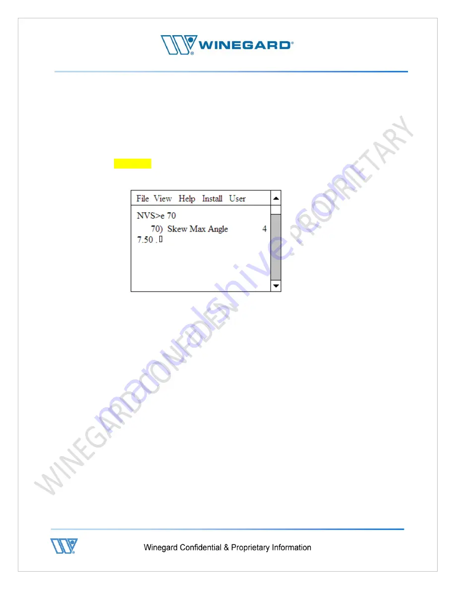
At the “NVS>” prompt, type “e 70” and press enter.
a.
The value displayed is the current maximum value for the skew.
b.
CAUTION : The system is now ready to enter the new value. If the value
doesn’t need to be changed, press enter. Do not save the new values.
c.
The picture above depicts a typical value for a DT740 (47.5 degrees).
d.
This value may be different depending on model and skew configuration.
e.
If the system rotated past the zero degree skew position during skew motor
calibration, then this value is too large.
f.
If the system did not reach the zero degree position during skew motor
calibration, then this value is too small.
8.
Type the new value into the IDU and press enter.
a.
Start with small value changes.
b.
To increase the Skew Max Angle 1 degree type “48.5” and press enter.
9.
Press enter again and the system will display the “NVS>” prompt.
10.
From the “NVS>” prompt, type “s” and press enter.
a.
This saves the new value into memory.
11.
The system needs to be power cycled in order for the new values to take effect.
a.
Once the system has been power cycled, start back at step 1 and calibrate the
skew motor.
8.4.2 - Calibration of the Azimuth Home Position
Summary of Contents for 2-WAY SATELLITE INTERNET SYSTEM
Page 10: ...P a g e 10 3 Open lids on both sides as shown below ...
Page 19: ...P a g e 19 ...
Page 56: ...P a g e 56 ...
Page 81: ...P a g e 81 9 4 Wiring Diagram User Supplied Device ...


