background image

26

2. 

Operation

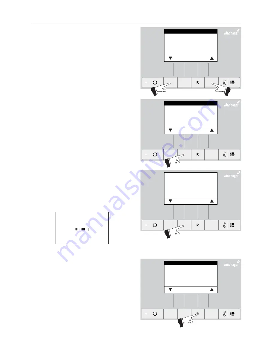
Use the arrow keys to mark the sub-menu item “Con-
firm stage 1 cleaning“ or “Confirm stage 2 cleaning“ – 
Fig. 54.

Fig. 54   

Confirm stage 1 cleaning

Confirm stage 2 cleaning
Pellet consumption
Time
Feed operating mode
Time profile feed


Choose 

Back 

Confirm the marked sub-menu item “Confirm stage 1 
cleaning“ or “Confirm stage 2 cleaning“ by pressing the 

Choose

 button – Fig. 55.

Pressing  the  Yes  button  resets  the  boiler  cleaning  – 
Fig. 56. The display shows “Parameter is saved” for a 
few seconds (Fig. 57) and then changes back to the pre-
vious level – Fig. 58.

Fig. 55   

Confirm stage 1 cleaning

Confirm stage 2 cleaning
Pellet consumption
Time
Feed operating mode
Time profile feed


Choose 

Back 

Fig. 56   

Was stage 1 cleaning performed 
according to the instructions?

Confirm


Yes  

Back 

The menu item or sub-menu item is exited by pressing 
the Back button (Fig. 58) or after a delay of 10 minutes.

Fig. 57   

Fig. 58   

Confirm stage 1 cleaning

Confirm stage 2 cleaning
Pellet consumption
Time
Feed operating mode
Time profile feed


Choose 

Back 

Parameter is saved

(Animated symbol)

Summary of Contents for BioWIN 2

Page 1: ...PELLETS Operating Manual BioWIN 2 Pellet central heating boiler Output range 3 to 25 9 kW 07 2014 093406 01 ...

Page 2: ... Functional description function elements and operating controls 10 2 2 1 BioWIN 2 Klassik 10 2 2 2 BioWIN 2 Premium 11 2 2 3 BioWIN 2 Exklusiv 12 2 3 Check before initial start up 13 2 4 Filling the reserve supply container 13 2 4 1 BioWIN 2 Klassik Manual filling 13 2 4 2 BioWIN 2 Premium and Exklusiv fully automatic filling 13 2 5 InfoWINplus 14 2 6 Operating modes 15 2 6 1 OFF mode 15 2 6 2 ON...

Page 3: ...l 49 3 4 Empty ash pan and remove ash from underneath the coasting surface BioWIN 2 Klassik and Premium BWK BWP 49 3 5 Empty the ash box BioWIN 2 Exklusiv BWE 50 3 6 Combustion chamber and Burner pot cleaning 52 3 6 1 Cleaning the thermocontrol sensor and down chute 52 3 6 2 Burner pot cleaning 53 3 7 Clean top coasting surfaces and blower wheel 54 3 8 Exhaust pipe to flue 55 3 9 Water tank level ...

Page 4: ... the manufacturer cannot be held liable in the following cases Incorrect use of the unit Failure to perform proper maintenance Incorrect installation of the unit 1 1 2 Installer s obligations The installer is the person responsible for installing the unit The installer must comply with the following instruc tions Read and follow all instructions supplied with the unit Carry out installation in acc...

Page 5: ...r A self test is performed following a power failure during combustion and then operation is continued automatically 1 3 2 Burner pot Attention Never fill the burner pot with pellets by hand Excessive combustion material in the burner pot me ans that the pellets will not be ignited optimally Too much low temperature carburisation gas will be generated and this can lead to deflagration Please note ...

Page 6: ...torage room immediately and seek medical advice Attention Do not attempt to enter an unaired storage room particularly buried tanks 1 3 4 Combustion air Never seal openings that have been provided for letting air in and out 1 4 Fuel To ensure that your new heating system provides long term reliable service the following must be observed Quality of pellets must be in accordance with EN 14961 2 A1 T...

Page 7: ...ial start up cannot be carried out if any of these points are neglected The customer will be charged for any unnecessary costs arising as a result Start up and maintenance by Windhager Customer Service or a customer service partner are part of the gua rantee requirements of the enclosed guarantee limitations Note During the first few weeks after start up condensation can occur in the combustion ch...

Page 8: ...least 15 minutes before the store is filled Fig 2 Press the ON OFF button Never switch off using the emergency OFF switch Tip To prevent negative pressure arising in the pellet boiler open the combustion chamber door see Fig 3 and also section 2 1 and leave open during the filling process Fig 2 Switching off BioWIN Fig 3 Opening combustion chamber door during the filling process 002357 00 01 2010 ...

Page 9: ... via the On Off switch see Fig 2 and allowed to cool down no reading in display Raise cover and remove unscrew Allen key Fig 5 Insert the Allen key turn a quarter turn to the left and open the cladding door Fig 6 7 Fig 5 Raise cover and remove unscrew Allen key Fig 6 Opening the cladding door with the Allen key 1 4 Fig 7 Cladding door open Allen key Folder instructions ...

Page 10: ...er pot has cooled down 2 2 1 BioWIN 2 Klassik The reserve supply container is loaded by hand The heating surfaces are cleaned manually using the cleaning lever The cleaning residues from the heating surfaces and the combustion residues from the burner pot drop into the ash pan In the event of cleaning request the ash has to be removed by hand 1 Inspection cover Reserve supply container under cover...

Page 11: ...on probes is executed automatically The system changes to the next suction probe after the reserve supply container has been filled a certain number of times This means the storage room is evenly emptied to a large extent 1 Inspection cover Reserve supply container under cover 2 Water tank for burn back safeguard behind reserve supply container 3 Pellet reserve supply container 4 Fully automatic p...

Page 12: ...7 8 9 10 11 12 14 Fig 10 BioWIN 2 Exklusiv without combustion chamber door and with open cladding door 1 Inspection cover Reserve supply containe under cover 2 Water tank for burn back safeguard behind reserve supply container 3 Pellet reserve supply container 4 Fully automatic pellet feed 5 Device fuse T 6 3 A 6 Safety thermostat for auger tube 7 Safety thermostat for boiler temperature 8 InfoWIN...

Page 13: ... 1 BioWIN 2 Klassik Manual filling Open reserve supply container cover and fill reserve container up to max 1 cm below the edge Close the cover Operation with external supply of combustion air The lid on the integral fuel hopper is monitored by a safety switch The boiler cannot be operated when the lid is open If the lid is opened during operation after 4 mins the boiler switches to burnout 2 4 2 ...

Page 14: ...for longer than one hour the display is switched off completely and only the green LED is lit The display is switched on again when a button is pressed or if another operating mode is activated The various operating modes are displayed on InfoWINplus together with the corresponding operating phases The following operating modes exist OFF ON with self test lighting ON lighting OFF Pellet feed Solid...

Page 15: ...ttons Fig 14 If the self test was unsuccessful an information mes sage e g information fault alarm is displayed see sections 4 Lighting ON OFF The display lighting switches off automatically after 10 minutes Fig 15 Pressing one of the six buttons swit ches the lighting on again for 10 minutes InfoWINplus identifies and stores the various opera ting modes and states Once the system is switched on o...

Page 16: ...ntrol panel automatically switches over between pellet and solid fuel buffer mode Combustion of the BioWIN 2 is stopped when the WVF or B PLM module sends the request to switch over to solid fuel buffer mode Fig 18 Following this the system switches over to solid fuel buffer mode and the Bio WIN 2 burner is locked Fig 19 If the pellet boiler is switched off using the ON OFF button on the InfoWINpl...

Page 17: ...igh ting is switched off after the lighting timer has counted down 10 minutes the function or display remains un changed Pressing the Cancel button terminates the function Fig 21 The boiler returns to automatic operation Setpoint adjustment for manual operation By pressing the or button the display switches to the setpoint adjustment mode Fig 22 Using the or button can change the setpoint in 1 K s...

Page 18: ...nutes Pressing the corresponding button enables the boiler to be operated with 30 or 100 output Fig 25 The lighting is switched off after the lighting timer has coun ted down 10 minutes the function or display remains unchanged Only the lighting is switched on when the button is first pressed The operating time is reset to 45 minutes when the Manual operation chimney sweeper function button is pre...

Page 19: ...stem switches over to fla me stabilisation 2 7 4 Flame stabilisation Following the ignition procedure even combustion is established and then the system switches over to modulation mode 2 7 5 Modulation mode The burner is in modulation mode The output is infinitely varied between 30 and 100 2 7 6 Burnout Combustion is stopped Pellet transport into the burner pot is stopped the In duced draught fan...

Page 20: ...le Firing automate BW II Boiler no Heat generator nummer Operating time until Stage 1 cleaning ca 250 h Stage 2 cleaning ca 500 h Full service ca 1000 h Back 2 8 1 Operating time until stage and full service Display of the operating time in hours remaining until the next cleaning main cleaning and maintenance processes Note The operating time remaining until the next boiler cleaning de pends on th...

Page 21: ...put is displayed in The boiler output modulation mode can be set from 30 to 100 Operating hours The total number of burner operating hours is displayed Burner starts The number of burner starts of the BioWIN 2 is displayed 2 8 4 Software version Display module The current software version of the display module InfoWINplus is displayed Firing automate The current software version of the firing auto...

Page 22: ...on Fig 45 or after a delay of 10 minutes Information Only trained service personnel may per form system modifications on the Service level 1 only displayed when an MESplus control is present and this has been adjusted by a trained service technician in the basic settings Fig 42 Boiler temperature Operating phases Info Menu 42 C Fig 43 Operator level Service level Information level MES Module1 Choo...

Page 23: ...ge 1 cleaning Pellet consumption Feed operating mode2 Probe switching2 all probes only zone 2 only zone 1 Only probe 1 Only probe 2 Only probe 3 Only probe 4 Only probe 6 Only probe 5 Only probe 7 Only probe 8 Confirm stage 2 cleaning Time Time profile feed2 Heating surf cleaning with enable time with enable time without time control ausgeschaltet with enable time Start finish with start time Star...

Page 24: ...section 2 9 1 4 Time profile feed see section 2 9 1 5 Probe switching see section 2 9 1 6 Heating surf cleaning see section 2 9 1 7 Note The menu items Feed operating mode Time profile feed and Probe switching are only shown if a feed or probe switching function is provided and activated on the service level 1 only displayed when an MESplus control is present and this has been adjusted by a traine...

Page 25: ...ned service technician in the basic settings Boiler temperature Operating phases Lighting ON 42 C Boiler temperature Operating phases Info Menu Operator level Service level Information level MES Module1 Choose Back 42 C The menu item or sub menu item is exited by pressing the Back button Fig 50 or after a delay of 10 minutes Fig 50 Confirm stage 1 cleaning Confirm stage 2 cleaning Pellet consumpti...

Page 26: ...aning Fig 56 The display shows Parameter is saved for a few seconds Fig 57 and then changes back to the pre vious level Fig 58 Fig 55 Confirm stage 1 cleaning Confirm stage 2 cleaning Pellet consumption Time Feed operating mode Time profile feed Choose Back Fig 56 Was stage 1 cleaning performed according to the instructions Confirm Yes Back The menu item or sub menu item is exited by pressing the ...

Page 27: ...r level by pressing the Choose button Fig 60 Use the arrow buttons to select the Pellet consumpti on sub menu item Fig 61 1 only displayed when an MESplus control is present and this has been adjusted by a trained service technician in the basic settings Fig 59 Boiler temperature Operating phases Info Menu Fig 60 Operator level Service level Information level MES Module1 Choose Back Fig 61 Confirm...

Page 28: ...el Fig 65 Fig 62 Confirm stage 1 cleaning Confirm stage 2 cleaning Pellet consumption Time Feed operating mode Time profile feed Choose Back Fig 63 Reset pellet consumption from last bulk fill Confirm Yes Back The menu item or sub menu item is exited by pressing the Back button Fig 65 or after a delay of 10 minutes Fig 64 Fig 65 Confirm stage 1 cleaning Confirm stage 2 cleaning Pellet consumption ...

Page 29: ...es the lighting and display on Press the Menu button Fig 66 Confirm the selected menu item Operator level by pressing the Choose button Fig 67 Use the arrow buttons to select the Time sub menu item Fig 68 1 only displayed when an MESplus control is present and this has been adjusted by a trained service technician in the basic settings Fig 66 Boiler temperature Operating phases Info Menu Fig 67 Op...

Page 30: ... previous level Fig 73 Fig 69 Confirm stage 1 cleaning Confirm stage 2 cleaning Pellet consumption Time Feed operating mode Time profile feed Choose Back Fig 70 Time 13 50 Save Back Fig 71 Time 13 50 Save Back Fig 72 Parameter is saved Animated symbol The menu item or sub menu item is exited by pressing the Back button Fig 73 or after a delay of 10 minutes Fig 73 Confirm stage 1 cleaning Confirm s...

Page 31: ...ol Pressing one of the six buttons switches the lighting and display on Press the Menu button Fig 74 Confirm the selected menu item Operator level by pressing the Choose button Fig 75 1 This is only displayed if there is a feed system fitted and this has been set in the service level by trained service personnel 2 only displayed when an MESplus control is present and this has been adjusted by a tr...

Page 32: ...rating mode Time profile feed Choose Back Fig 78 The arrow buttons select the required sub menu Fig 78 Pressing the Save button saves the changed Feed operating mode Fig 79 The display shows Parameter is saved for a few seconds Fig 80 and then changes back to the previous level Fig 81 with start time Select this if you want the feed to start at the same time every day Functional description The re...

Page 33: ...ed menu item Operator level by pressing the Choose button Fig 83 The arrow buttons select the Time profile feed sub menu Fig 84 1 This is only displayed if there is a feed system fitted and this has been set in the service level by trained service personnel 2 only displayed when an MESplus control is present and this has been adjusted by a trained service technician in the basic settings Fig 82 Bo...

Page 34: ...time Start 07 00 End 22 00 The arrow buttons select the Start or End times to be changed Fig 86 Pressing the or buttons changes the time in 1 min steps Fig 88 Confirm the selected time by pressing the Choose but ton Fig 87 Fig 85 Confirm stage 1 cleaning Confirm stage 2 cleaning Pellet consumption Time Feed operating mode Time profile feed Choose Back Fig 86 Feed with enable time Start 07 00 End 2...

Page 35: ...Back button Fig 91 or after a delay of 10 minutes Fig 89 Feed with enable time Start 07 30 End 22 00 Save Back Feed with enable time Start 07 30 End 22 00 Choose Back The display shows Parameter is saved for a few se conds Fig 90 and then changes back to the previous level Fig 91 Fig 90 Parameter is saved Animated symbol Fig 91 ...

Page 36: ...ub menu item is exited by pressing the Back button Fig 95 or after a delay of 10 minutes without time control or switched off No setting is possible here in the Time profile feed menu item if the without time control or switched off setting is active in the Feed operating mode menu item see section 2 9 1 4 Fig 96 The menu item or sub menu item is exited by pressing the Back button Fig 96 or after ...

Page 37: ... switching Removal from probe 1 and probe 2 automated switching Removal from probe 3 and probe 4 automated switching Removal from probe 1 only no switching Removal from probe 2 only no switching Removal from probe 3 only no switching Removal from probe 4 only no switching Suction turbine with 6 probes all probes only zone 1 only zone 2 only probe 1 only probe 2 only probe 3 only probe 4 only probe...

Page 38: ...g 98 The arrow buttons select the probe switching sub menu Fig 99 1 only displayed when an MESplus control is present and this has been adjusted by a trained service technician in the basic settings Fig 97 Boiler temperature Operating phases Info Menu Fig 98 Operator level Service level Information level MES Module 1 Choose Back Fig 99 Probe switching Heating surf cleaning Choose Back 42 C ...

Page 39: ...be switching Heating surf cleaning Choose Back Fig 101 Probe switching all probes only zone 1 only zone 2 Only probe 1 Save Back Fig 102 Probe switching all probes only zone 1 only zone 2 Only probe 1 Save Back Fig 103 The display shows Parameter is saved for a few se conds Fig 103 and then changes back to the previous level Fig 104 The menu item or sub menu item is exited by pressing the Back but...

Page 40: ... Duration 0 h Setting range 0 10 h Pressing one of the six buttons switches the lighting and display on Press the Menu button Fig 105 Confirm the selected menu item Operator level by pressing the Choose button Fig 106 The arrow buttons select the Heating surf cleaning submenu Fig 107 1 only displayed when an MESplus control is present and this has been adjusted by a trained service technician in t...

Page 41: ... period can be changed by 1 minute and Duration is adjusted by 1 hour Fig 111 Confirm the selected time by pressing the choose but ton Fig 110 Fig 108 Probe switching Heating surf cleaning Choose Back Fig 109 Heating surf cleaning Initiate off period 20 00 Duration 0 h Choose Back Fig 110 Heating surf cleaning Initiate off period 20 00 Duration 0 h Choose Back Fig 111 Heating surf cleaning Initiat...

Page 42: ...anges back to the previous level Fig 114 The menu item or sub menu item is exited by pressing the Back button Fig 114 or after a delay of 10 minutes Fig 112 Heating surf cleaning Initiate off period 20 00 Duration 10 h Save Back Fig 113 Heating surf cleaning Initiate off period 20 00 Duration 10 h Choose Back Fig 114 Parameter is saved Animated symbol ...

Page 43: ...oWIN 2 as sembly instructions The menu item or sub menu item is exited by pressing the Back button Fig 117 or after a delay of 10 minutes 1 only displayed when an MESplus control is present and this has been adjusted by a trained service technician in the basic settings Operator level Service level Information level MES Module 1 Choose Back Service level only for trained service personnel 5sec Par...

Page 44: ...ee their respective Operating instructions Boiler switching on MESplus system control to automatic operation 1 Press the ON OFF button on the InfoWINplus panel the lighting and display are switched on the signal lamp lights green and a self test is performed see also section 2 6 2 After a successful self test and if a setpoint is transferred by the system control the BioWIN 2 automatically starts ...

Page 45: ...atically starts operation 2 Set both manual switches to the Automatic position 3 Set the operating mode switch on the REG standard control unit RAM 786 RAM 850 to Automatic operation please refer to the separate Operating instructions The REG standard control unit RAM 786 RAM 850 installed in the living area is used to operate the system set the desired temperature and operating times The time mus...

Page 46: ...er temperature will be maintained at the selected temperature 60 to 75 C Exercise caution if you have under floor heating Emergency operation of boiler reservoir with feed pump 1 There must be power to the boiler The unit is switched on otherwise press the ON OFF button on the InfoWINplus operating unit 2 Select Manual operation on the InfoWINplus unit see section 2 6 5 3 Set the manual switch to ...

Page 47: ...Emergency operation Stage 1 cleaning FE 320 Empty the ash pan and Remove ash from coasting surface see section 3 4 Clean the thermocontrol sensor see section 3 6 1 Confirm stage 1 cleaning see section 3 1 1 Stage 1 cleaning IN 522 or Emergency operation Stage 1 cleaning FE 322 Emptying the ash pan see section 3 5 Clean combustion chamber and burner pot see section 3 6 Confirm stage 1 cleaning see ...

Page 48: ... 1 cleaning performed according to the instructions Confirm Yes Back 3 2 Cleaning and operating implements 1 Cleaning brush 2 Spatula 3 Allen key 4 Scratcher only BioWIN 2 Klassik and Premium 5 Pellet pile1 accessory for BioWIN 2 Premium Exklusiv only 6 Folder containing instructions 1 2 3 4 5 Fig 125 Cleaning and operating implements Fig 126 In the door cleaning brush and spatula Fig 127 Under co...

Page 49: ...ustible container on non combustible base for at least 48 hours Note Small amounts of ash can be used in the garden as fertiliser Larger amounts of ash should be disposed of together with other residual waste please observe the applicable regulations Switch off the BioWIN 2 with the ON OFF button on the InfoWINplus Fig 128 and wait until the display has gone out ca 20 min Open cladding door and co...

Page 50: ...re ash in lockable and non combustible container on non combustible base for at least 48 hours Note Small amounts of ash can be used in the garden as fertiliser Larger amounts of ash should be disposed of together with other residual waste please observe the applicable regulations Switch off the BioWIN 2 with the ON OFF button on the InfoWINplus Fig 133 and wait until the display has gone out ca 2...

Page 51: ...ll the way back in Note The size of the box is related to the max ash content of the pellets If the ash box is not full when a cleaning request is issued then ash content will be less Fig 135 Pulling out handle Fig 136 Opening the bracket fastener Fig 137 Moving container slightly to the left Fig 138 Taking out container Fig 139 Open the side bracket fasteners remove cover Slide container slightly...

Page 52: ... the combustion chamber door during operation Always switch the boiler off first with the ON OFF button and wait until burnout mode has finished Fig 141 It is essential to let the combustion chamber cool down before cleaning Attention Before cleaning with a vacuum cleaner check that there are no longer any embers in the combus tion residue Open cladding door and combustion chamber door Fig 142 see...

Page 53: ...he burner pot Fig 150 remove the primary air pin and carefully clean the holes with a small screwdriver or drill bit if necessary holes must be clear Fig 151 152 All secondary air holes in the burner pot must be kept clear Fig 153 Fig 150 Vacuum out the burner pot Fig 151 Take out the primary air pin Fig 152 Clean the primary air pin carefully Fig 153 Clean the secondary air holes in the burner po...

Page 54: ...on 3 1 1 Fig 154 Vacuum out the primary air tube in the centre of the burner pot 3 7 Clean top coasting surfaces and blower wheel Switch off the BioWIN 2 with the ON OFF button on the InfoWINplus Fig 156 and wait until the display has gone out ca 20 min Warning of hot surface risk of burns Before touching the screw connections and coasting surface cover you must switch off the boiler and let it co...

Page 55: ... out the ash from the coasting surfaces Fig 163 Fig 162 Cleaning the coasting surfaces Fig 163 Vacuum out the ash 3 8 Exhaust pipe to flue Clean vacuum out the exhaust pipe pipe connecting the pellet boiler and flue around the cleaning aperture Fig 164 2 1 1 3 Fig 164 Cleaning openings in exhaust pipe view from front dra wing does not show exhaust pipe insulation 1 Cleaning aperture in exhaust pip...

Page 56: ...be emergency filled by hand via the inspection cover Switch off the BioWIN 2 with the ON OFF button on the InfoWINplus Fig 166 and wait until the display has gone out ca 20 min Please note Risk of crushing from rotating auger Before opening the inspection cover always disconnect the boiler from the power supply Discon nect the mains power plug Remove top cover Fig 167 Disconnect the mains power pl...

Page 57: ...r using a small bucket or shovel to do so or attach pellet pile1 accessory and then add the pellets Fig 175 Mount the inspection cover as an anti contact protection in front of the opening to the auger conveyor Fig 175 Attention In the BioWIN 2 model with external combustion air supply the inspection cover must always be closed when the system is in operation Fig 168 Disconnecting mains power plug...

Page 58: ...By working through these steps in reverse order Fig 172 Remove the screws and take off the inspections cover Fig 173 Feed unit flap Proximity switch with telltale Fig 174 Proximity switch feed unit Fig 175 Mount pellet pile and inspections cover ...

Page 59: ...uppliers recommend fully emptying the storage room every 2 3 years You can deactivate automatic changeover between the three suction probes using the InfoWINplus see section 2 9 1 4 This allows you to fully empty the storage room for one probe You can then con tinue heating with the other suction probes If you repeat this process each year with different probes you will be renewing your entire sto...

Page 60: ...er rectifying the cause of the information fault or alarm message In these cases Reset is displayed in the menu line Fig 178 If Reset is not displayed in the menu line the boiler starts operating again automatically after the cause of the information fault or alarm message has been rectified If you wish to call Windhager Customer Service or your customer service Partner due to a malfunction please...

Page 61: ... cleaning Please note that the pellet boiler needs to be cleaned within the next 50 hours of operation see section 3 5 3 6 Once the cleaning has been completed it must be confirmed see section 2 9 1 1 IN 523 Stage 2 cleaning Perform stage 2 cleaning according to operation manual Push next to confirm stage 2 cleaning has been completed Please note that the main cleaning of the pellet boiler needs t...

Page 62: ...e sensor defective Check the flue gas temperature sensor and connections It is not possible to display the flue gas temperature No effect on operation Replace the flue gas temperature sensor inform Windhager Customer Ser vice or a heating technician FE 320 Emergency operation Stage 1 cleaning Empty the ash pan remove ash from heat exchanger base Clean thermocontrol sensor Push next to confirm stag...

Page 63: ...tomer Service or a heating technician c Inform Windhager Customer Service or a heating technician Emergency operation Switch off the feed unit see section 2 9 1 4 Fill the reserve supply container with pellets by hand see section 3 10 boiler is allowed to continue operating without feed FE 387 Communication failure with Firing Automate Appuyer la touche reset pendant 5 sec mini mum a Check the con...

Page 64: ...nit does not move any more and cannot be closed Boiler swit ches to burnout and is locked a The shut off unit is blocked Press the Reset button and if the alarm mes sage does not go away contact Windhager Customer Service or a heating technician b Ash removal motor defective inform Windhager Customer Service or a heating technician c Limit switch on the shut off unit is defective inform Windhager ...

Page 65: ...ting technician AL 130 Combustion chamber temperature too low Perform stage 2 cleaning according to opera tion manual Press reset The flame goes out in modulation mode The boiler switches to burnout mode a The main cleaning of the pellet boiler has to be completed see section 3 4 3 9 Once the main cleaning process has been completed it must be confir med see section 3 1 1 b Check the ash box see s...

Page 66: ...ct position and are sealed danger of inleaked air f Combustion chamber pressure switch is defective inform Windhager Customer Service or a heating technician AL 171 Maximum heating time exceeded Clean burner pot Press reset No flame formation when heating up Heating up procedure is cancelled a The main cleaning of the pellet boiler has to be completed see section 3 4 3 9 Once the main cleaning pro...

Page 67: ...nton Windhager Straße 20 A 5201 Seekirchen Subject of the declaration Pellet boiler series BioWIN 2 The units conform to the relevant requirements of the Machinery Directive 2006 42 EC and the EMC Directive 2004 108 EC In addition we declare that we have applied the following technical standards EN 303 5 2012 10 EN 60335 1 2012 10 EN 61000 6 2 2005 EN 61000 6 3 2007 A1 2011 Seekirchen 16 6 2014 WI...

Page 68: ...hat the boiler and related accessories be properly installed and started by Windhager Customer Service or Customer Service Partner otherwise the manufacturer s warranty will not be honored Malfunctions resulting from improper operation or adjustment as well as use of poor or not recommended fuel types are not covered by the warranty Further the warranty shall be void if equipment other than those ...

Reviews: