background image


030-300408 Rev. B 

125 

August 2005 


VersaLink™  Gateway (Model 327W)  


User Guide 


13.6.9    RIP 


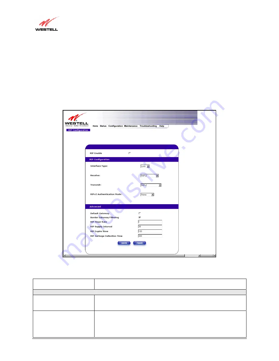
The following details will be displayed if you select 

RIP

 from the 

Advanced WAN

 menu. If you change any 

settings in this screen, click on 

save. 

If you click on 

reset,

 this screen will refresh and display your last saved RIP 

configuration. 


RIP (Routing Interface Protocol) is a dynamic inter-network routing protocol primarily used in interior routing 
environments. A dynamic routing protocol, as opposed to a static routing protocol, automatically discovers routes 
and builds routing tables. 


                           Note: In this screen, VersaLink represents ‘Gateway.’  


RIP Enable 

Factory Default = DISABLED 
If this box is checked, RIP will be Enabled (turned ON). 

RIP Configuration 

Interface Type 

LAN: Select this if you are configuring RIP for the LAN side. 
WAN: Select this if you are configuring RIP for the WAN side. (WAN side is 
receive only.) 

Receive 

The version of RIP to be accepted. 
Possible responses are: 
None 
RIPv1 
RIPv2 

Summary of Contents for Versalink 327W

Page 1: ...Copyright 2005 Westell Inc 030 300408 Rev B VERSALINK GATEWAY MODEL 327W USER GUIDE...

Page 2: ...6 2 Before you begin 12 6 3 Microfilters 12 6 4 Hardware Installations 13 7 INSTALLING THE USB DRIVERS 18 7 2 Installing the USB Drivers for Windows ME 24 7 3 Installing the USB Driver for Windows 20...

Page 3: ...Trigger Ports 129 14 4 Adding Local Trigger Ports 130 14 5 Static NAT 131 14 6 Enabling Static NAT 132 14 7 Disabling Static NAT 133 15 MAINTENANCE 135 15 1 Backup Restore 135 15 2 Firewall Log 136 15...

Page 4: ...eliminating the need for dedicated phone lines for voice and data needs VersaLink supports a variety of networking interfaces such as wireless 802 11b g g ADSL Ethernet and the following optional feat...

Page 5: ...which can provide 1 cm separation distance from the antenna to the body of the user or a nearby person Thin laptop computers may need special attention to maintain antenna spacing while operating Thi...

Page 6: ...ed equipment This certification means that the equipment meets certain telecommunications network protective operations and safety requirements as prescribed in the appropriate Terminal Equipment Tech...

Page 7: ...that the sum of the Ringer Equivalence Numbers of all the devices does not exceed five Users should ensure for their own protection that the electrical ground connections of the power utility telephon...

Page 8: ...requires an available Ethernet port with a 10 100 Base T Network Interface Card NIC installed WIRELESS IEEE 802 11g Pentium or equivalent class machines Microsoft Windows 98 ME 2000 or XP or Macintos...

Page 9: ...ted to the associated port Solid Green Link Established Flashing Green Wireless LAN activity is present traffic in either direction WIRELESS OFF Modem power is OFF or No Link Solid Green USB link esta...

Page 10: ...ptional and if UPLINK is not enabled in the ini file the Gateway will use DSL and Wireless only 5 3 Connector Descriptions The following chart displays the connector types SYMBOL NAME TYPE FUNCTION DS...

Page 11: ...bles list the pinout descriptions DSL Pinouts Pinout Description 1 2 5 6 Not Used 3 DSL Tip 4 DSL Ring USB Pinouts Pin Name Description Cable Color 1 VBUS Vcc 5 Vdc Red 2 D Data White 3 D Data Green 4...

Page 12: ...Power Supply RJ 45 Ethernet cable USB cable RJ 11 Phone cable SMA Antenna Westell CD ROM containing User Guide in PDF format Quick Start Guide 6 3 Microfilters ADSL signals must be blocked from reachi...

Page 13: ...our Ethernet card 1 Connect the power supply cord to the power connector marked DC 12V on the rear panel of VersaLink Plug the other end of the power supply into a wall socket 2 Connect the DSL phone...

Page 14: ...be configured with the SSID in order to communicate with VersaLink before you begin the account setup and configuration procedures Later for privacy you can change the SSID by following the procedures...

Page 15: ...power connector marked DC 12V on the rear panel of VersaLink Plug the other end of the power supply into a wall socket 5 Connect the DSL phone cable from the connector marked on the rear panel of Vers...

Page 16: ...able from connector marked on the rear panel of VersaLink to the DSL equipped telephone line jack on the wall IMPORTANT Do not use a DSL filter on this connection You must use the phone cord that was...

Page 17: ...the rear panel of VersaLink to the DSL equipped telephone line jack on the wall IMPORTANT Do not use a DSL filter on this connection You must use the phone cord that was provided with the kit 3 Connec...

Page 18: ...SB Driver for Windows ME Windows 2000 Installing the USB Driver for Windows 2000 Windows XP Installing the USB Driver for Windows XP 7 1 1 CD ROM Installation 1 Place the CD ROM that you received in t...

Page 19: ...Rev B 19 August 2005 VersaLink Gateway Model 327W User Guide Figure 5 Windows 98 SE 2 Windows 98 SE Select Search for the best driver for your device Recommended See Figure 6 Click Next Figure 6 Wind...

Page 20: ...er Figure 7 Windows 98 SE Note If Figure 7 does not appear at this step and Figure 8 appears with the text USB Composite device C Windows Inf USB Inf do not continue Click Back to Step 3 and specify t...

Page 21: ...river Figure 9 The drive letter may vary Click Next Figure 9 Windows 98 SE 6 Windows 98 SE Remove the Westell CD from the CD ROM Drive Next insert the Windows operating system CD into the CD ROM Drive...

Page 22: ...he installation Figure 12 Windows 98 SE If the Operating System CD is not available or if Figure 12 pops up again you will have to manually specify the location of the files The required files may be...

Page 23: ...e 14 Click Finish Figure 14 Windows 98 SE 10 Windows 98 SE Click Yes to restart your computer Figure 15 Figure 15 Windows 98 SE Congratulations You have completed the software installation for the USB...

Page 24: ...VersaLink kit is inserted in the appropriate drive before continuing this installation 1 Windows ME After you connect VersaLink to your PC the Found New Hardware window will appear Figure 16 After a b...

Page 25: ...odel 327W User Guide 2 Windows ME Windows will display the location of the driver Figure 18 Click Next Figure 18 Windows ME 3 Windows ME The window below confirms that the PC has finished loading the...

Page 26: ...k is ready for use You must now go to section 8 for instructions on configuring VersaLink for Internet connection 7 3 Installing the USB Driver for Windows 2000 IMPORTANT Confirm that the CD ROM provi...

Page 27: ...000 The Install Hardware Device Drivers window appears Select Search for a suitable driver for my device recommended See Figure 23 Click Next Figure 23 Windows 2000 3 Windows 2000 The Locate Driver Fi...

Page 28: ...e 4 Windows 2000 The Driver Files Search Results window appears Figure 25 Note The drive letter may vary Click Next Figure 25 Windows 2000 5 Windows 2000 The window below confirms that the PC has fini...

Page 29: ...omputer has restarted VersaLink is ready for use You must now go to section 8 for instructions on configuring VersaLink for Internet connection 7 4 Installing the USB Driver for Windows XP IMPORTANT C...

Page 30: ...e PC has finished loading the drivers Figure 29 Click Finish Figure 29 Windows XP Congratulations You have completed the software installation for the USB drivers After the computer has restarted Vers...

Page 31: ...ce provider s installation manual to install the software required for your Internet connection NOTE Internet service provider subscriber software and connection requirements may vary Consult your Int...

Page 32: ...count parameters Account parameters are required before connecting to the Internet Account Parameters include Connection Name the Connection Name is a word or phrase that you use to identify your acco...

Page 33: ...from your Internet service provider The actual VPI VCI values may vary according to your ISP Click on next NOTE Depending on your Internet Service Provider the VPI VCI screen may come pre configured a...

Page 34: ...ce provider Click on next When the SET UP COMPLETE screen appears you have successfully completed your Account Profile setup Click done NOTE Depending on your Internet Service Provider the PROTOCOL sc...

Page 35: ...screens If you did not change any of these values this pop up screen will not appear and the Gateway will not be reset If your Gateway s connection setting is set to Always On and you have changes any...

Page 36: ...ection Overview section see the following Home page If the status reads No DSL Connection check the DSL physical connection explained in section 6 INSTALLING THE HARDWARE of this User Guide NOTE If no...

Page 37: ...ccessful DSL SYNC has been established The connection rate values represent the transmission speed of your DSL line The Gateway may take time to report these values Click on the Connect button to esta...

Page 38: ...will display UP If the connection setting is set to Manual you must click on the Connect button to establish a PPP session Once the PPP session has been established PPP Status displays UP you may proc...

Page 39: ...del 327W User Guide After a PPP session has been established the PPP Status will display UP Congratulations You may now browse the Internet For example if you want to visit Westell s home page type ht...

Page 40: ...ion no IP connection to your Internet service provider However your DSL session will not be affected When you are ready to end your DSL session simply power down VersaLink via the power switch on Vers...

Page 41: ...se VersaLink s Ethernet installation Refer to section 6 INSTALLING THE HARDWARE Open the System Preference Screen After you have connected the Westell VersaLink to the Ethernet port of your Macintosh...

Page 42: ...on at the System Preferences screen the Network screen will be displayed Select New Location from the Location field Name the New Location After selecting New Location from the Network screen the foll...

Page 43: ...onnection To verify that the computer is communicating with VersaLink follow the instructions below 1 Go to the Apple icon in the upper right corner of the screen and select System Preferences 2 From...

Page 44: ...nt In the address window of your Internet Explorer web browser type http dslrouter Press Enter on your keyboard The Getting Started screen will be displayed You may now begin your Account Setup Refer...

Page 45: ...030 300408 Rev B 45 August 2005 VersaLink Gateway Model 327W User Guide The following sections explain the advanced features of VersaLink This Page Intentionally Left Blank...

Page 46: ...you how to make changes to VersaLink s settings A menu is displayed at the top of each screen and will allow you to navigate you to the various configuration options of your VersaLink Gateway If you a...

Page 47: ...e set up your account profile and established your PPP session as discussed in section 8 the following settings will be displayed when you click on your Home page Click on profile editor to edit your...

Page 48: ...click on OK in the pop up screen to save your new connection If you do not want to add a connection profile click on Close in the New Connection screen NOTE NAT Profiles allow you to create specific s...

Page 49: ...e preceding screen the Edit My Connection screen will appear Follow the steps in the Edit My Connection screen to change your existing connection profile which you set up in section 8 If you do not wa...

Page 50: ...ature allows the Gateway to automatically re establish your PPP session on demand anytime your PC requests Internet activity for example browsing the Internet email etc When you have traffic it may ca...

Page 51: ...mation Connection Rate This field will let you know if you have a DSL signal and the DSL rate at which you are connected Connection Status This field will show how much information was received IN or...

Page 52: ...n Name This is from the connection profile that you established in section 8 Connection Duration This field will display how long your PPP session has been connected Status This field will display the...

Page 53: ...ingle Static IP SSI allows the user to share the WAN assigned IP address with one device on the LAN By doing this the device with the SSI becomes visible on the Internet Network Address Translation NA...

Page 54: ...in the window Click on enable NOTE The Single Static IP Configuration screen allows you to select the device on your LAN that will share your Single Static IP If you select a device and clicked on en...

Page 55: ...licked OK in the preceding screen the following screen will be displayed VersaLink will be reset and the new configuration will take effect After a brief delay the home page will be displayed Confirm...

Page 56: ...chose to enable User Configured PC wait for the Gateway to reset and then manually enter the WAN IP Gateway and Subnet mask addresses you obtained from your Internet service provider into a PC 13 1 2...

Page 57: ...set and the new configuration will take effect Click on OK If you clicked OK in the preceding screen the following screen will be displayed VersaLink will be reset and the new configuration will take...

Page 58: ...propriate ports on VersaLink are open and that the required application traffic can pass through your LAN For a list of supported services go to section 17 NAT Services NAT Profiles allow you to creat...

Page 59: ...rk Address Translation services that you have selected Service Name Drop down selection menu of NAT Network Address Translation service you can select to configure you VersaLink UPNP Enable Factory De...

Page 60: ...are ready to disable UPNP uncheck the UPNP Enable box in the Service Configuration screen If you click the UPNP Enable box in the Service Configuration screen a check mark will appear in the box and t...

Page 61: ...screen the following screen will be displayed The Gateway will be reset automatically and the new configuration will take effect After a brief delay the home page will be displayed Confirm that you ha...

Page 62: ...ou want to set up a different connection setting for a profile you can create new NAT profiles and customize them to your preference NOTE You may create up to four NAT profiles and attach an unlimited...

Page 63: ...rofile 1 from the Current Profile drop down arrow If you selected A New Service Profile 1 from the Current Profile drop down arrow the following screen will be displayed This screen shows that you hav...

Page 64: ...ing screen will be displayed By selecting the edit button you can make changes to your profile name and then add NAT services to or delete them from your profile Type your new NAT service profile name...

Page 65: ...NAT Profile screen the following pop up screen will be displayed Click OK to save your new profile settings If you click on Cancel your new profile settings will not be saved The following screen disp...

Page 66: ...pen and that the required application traffic can pass through your LAN For a list of supported NAT services go to section 17 NAT Services To add a NAT service select Services from the Configuration m...

Page 67: ...e displayed If you click OK you will allow incoming connections to be forwarded to a designated local PC If you click Cancel you will allow only outgoing connections from any local PC Click OK or clic...

Page 68: ...ervice you selected on your local area network You must either select the device from the Host Device drop down arrow or type an IP address in the field labeled IP Address If you click on Cancel the c...

Page 69: ...een will display the details of the selected NAT service If you click on the delete button in the Service Configuration screen you will remove that NAT service from your NAT service profile Click clos...

Page 70: ...ecurity allows customization through NAT configuration so that you can enable the traffic that you want to pass Low The Low security setting will allow all traffic except for known attacks With Low se...

Page 71: ...s that you do not change the settings in the User Defined Firewall Rules screen If you need to reset VersaLink to factory default settings push the reset button on the rear of VersaLink The informatio...

Page 72: ...set VersaLink to factory default settings push the reset button on the rear of VersaLink If you clicked save in the User Define Firewall Rules screen the following pop up screen will be displayed Clic...

Page 73: ...ugust 2005 VersaLink Gateway Model 327W User Guide If you select Help in the screen labeled User Defined Firewall Rules the following screen will be displayed This screen gives a detailed explanation...

Page 74: ...privacy you may change the Network Name SSID value in the Wireless Configuration screen to your desired value NOTE Client PCs can use any Wireless Fidelity Wi Fi 802 11b g g certified card to communic...

Page 75: ...he default selection Shared Key To use Shared Key authentication WEP must be enabled and a valid WEP key must be present Enabling WEP does not force the use of Shared Key authentication It is permissi...

Page 76: ...reshold If this value is larger than the MSDU size typically set by the fragmentation threshold no handshaking will be performed A value of zero will enable handshaking for all MPDUs Fragmented Thresh...

Page 77: ...ON ERP is used Local STA s If there are any associated stations than do not support ERP a protection algorithm is used to prevent contention Dynamic Similar to local STA s with the following extensio...

Page 78: ...Key Mapping Table in the Wireless Configuration screen WEP Key Select Enable is you want this WEP key enabled for the listed MAC Address MAC Address The MAC address assigned to the station for which y...

Page 79: ...When the MAC Filter is enabled only stations in the MAC Filter Table which are set to Allowed will have access to the AP Blocked This allows the station to remain in the table but no access to the Ver...

Page 80: ...ou select Advanced LAN from the Configuration menu NOTE If VersaLink is configured for ETHERNET PORT 1 VLAN will not be displayed You must configure VersaLink for DSLATM PORT to access VLAN in the Adv...

Page 81: ...nder Static Host Assignment type in the Host Name and the IP address and click Set IP Address Displays the IP address that is assigned to the Host Name Discover Local Devices This field displays a lis...

Page 82: ...y Model 327W User Guide The following screen displays a Host Name and an IP Address in the fields Now click on add If you clicked add the following screen will be displayed The Host Name and IP Addres...

Page 83: ...LAN configuration This option is only available if the Public LAN DHCP server is enabled NOTE These addresses will be overwritten if the Internet Service Provider supports dynamic setting of these va...

Page 84: ...ease Time is displayed in the format dd hh mm ss This value must be greater than 10 seconds Seconds must be between 0 and 59 minutes must be between 0 and 59 and hours must be between 0 and 23 dd days...

Page 85: ...d Off at DHCP Server the following screen will be displayed Click on save to save the DHCP Server setting If you clicked on save in the preceding DHCP Configuration screen the following pop up screen...

Page 86: ...7W User Guide 13 5 4 Enabling the DHCP Server If you want to enable your DHCP Server settings select Private LAN at the DHCP Server drop down arrow If you have recently disabled the DHCP Server for Pr...

Page 87: ...played automatically Click on save to save your DHCP Server setting If you click on reset your DHCP Server will be reset to factory default Private LAN is the factory default for the DHCP Server If yo...

Page 88: ...network behind VersaLink If you change the settings in this screen click save If you click on reset the changes will not take effect If you made changes and clicked on save the following pop up screen...

Page 89: ...p screens If this occurs check the settings in the Private LAN Configuration screen Warning Message Check Private LAN DHCP Settings Start Address is not part of the Subnet Check the value in the DHCP...

Page 90: ...public devices are visible on the Internet unlike a local NAT ed PC The example below shows four NAT ed PCs and one global PC The arrows show the data path for each flow Ethernet DSL WAN IP Router Mo...

Page 91: ...AN to bypass the NAT interface Public LAN IP Address Provides a Public IP Address if the service provider does not automatically provide one Public LAN Subnet Mask Provides a Public Subnet Mask if the...

Page 92: ...n the Public LAN Configuration screen and clicked save the following pop up screen will be displayed Click OK to save the new settings If you click on Cancel your new settings will not take effect NOT...

Page 93: ...than 10 seconds Check the values in the DHCP Lease Time fields Seconds must be between 0 and 59 Check the Seconds field at DHCP Lease Time Minutes must be between 0 and 59 Check the Minutes field at...

Page 94: ...guration 13 5 7 VLAN The following settings will be displayed if you select VLAN from the Advanced LAN menu VLAN Enable Factory Default DISABLED If this box is check VLAN will be Enabled This will all...

Page 95: ...n screen when the you are using the Bridge VLAN Bridge protocol See Advanced WAN section for configuring VC s refer to section 13 6 5 NOTE If you change the values in the VLAN Configuration screen and...

Page 96: ...ou must configure VersaLink for DSLATM PORT to access QOS in the Advanced WAN drop down menu Refer to section 13 6 2 1 for details 13 6 1 ATM Loopbacks If you select ATM Loopbacks from the Configurati...

Page 97: ...ast Bridge Multicast or Spanning Tree Protocol configurations in this screen click on the save filter settings button to allow these changes to take effect If you change any of the Status configuratio...

Page 98: ...VC which is specified by your Service Provider PPPoA Point to Point Protocol over ATM Asynchronous Transfer Mode PPPoE Point to Point Protocol over Ethernet Bridge Bridge Protocol Classical IPoA Inter...

Page 99: ...nnect the same two computer network segments Spanning Tree Protocol will allow the bridges to exchange information so that only one of them will handle a given message that is being sent between two c...

Page 100: ...he following screen will be displayed Click on OK If you click on Cancel the change will not take effect If you clicked on OK in the preceding pop up screen the following pop up screen will appear Ver...

Page 101: ...he WAN Ethernet Port select ETHERNET PORT 1 from the WAN PORT drop down arrow By selecting ETHERNET PORT 1 you will disable the VersaLink s DSL transceiver This will disable the DSL Port and allow the...

Page 102: ...the procedure defined under the Maintenance menu in section 15 1 Factory defaults become current configuration If you select ETHERNET PORT 1 from the WAN Port drop down arrow the following screen will...

Page 103: ...uration screen will be displayed if you click on the edit button adjacent to any of the Enabled protocols displayed in the WAN Configuration screen Note The Protocol must be enabled before you can edi...

Page 104: ...ich is defined by your Service Provider PCR Factory Default 100 Peak Cell Rate PCR The maximum rate at which cells can be transmitted across a virtual circuit specified in cells per second and defined...

Page 105: ...Failures Indicates number of continuous LCP echo non responses received before the PPP session is terminated LCP Echo Retry Duration The interval between LCP Echo transmissions with responses LCP Echo...

Page 106: ...receding screen the following screen will be displayed VersaLink will be reset and the new configuration will take effect After a brief delay the home page will be displayed Confirm that you have a DS...

Page 107: ...ode To configure VersaLink s protocol settings for PPPoE mode select WAN from the Advanced WAN menu The WAN Configuration screen will be displayed Next click on the edit button adjacent to any of the...

Page 108: ...e options listed in Protocol drop down arrow After you have made the configuration for this protocol select the set VC button If you click the set VC button the following pop up screen will be display...

Page 109: ...n screen will be displayed Next click on the edit button adjacent to any of the existing Enabled VC Virtual Connection protocols The VC1 Configuration screen will be displayed NOTE The protocol status...

Page 110: ...encapsulation of the IP protocol Status The protocol status VC 1 Bridge Settings Bridge A bridge is a layer 2 device that connects two segments of the same LAN that use the same protocol such as Ethe...

Page 111: ...lds and click on set VC VC 1 Bridge Settings Routed Bridge Mode The Mode you have selected to use with Bridge protocol DHCP Client Selecting a radio button allows you to either Enable or Disable the D...

Page 112: ...s the following screen will be displayed Enter the appropriate values in the fields and click on set VC VC 1 Bridge Settings Proxy Bridge Mode The Mode you have selected to use with Bridge protocol Ga...

Page 113: ...s and click on set VC VC 1 Bridge Settings VLAN Bridge Mode The Mode you have selected to use with Bridge protocol VLAN is used to assign VLAN tags to individual data ports on the modem VLAN ID Assign...

Page 114: ...must click the set VC button to save your VC settings If you click the set VC button the following pop up screen will be displayed Click on OK in the pop up screen If you click on Cancel the new sett...

Page 115: ...tings for ETHERNET PORT 1 To configure the Gateway s VC settings via the Ethernet uplink port select ETHERNET PORT 1 at the WAN Port drop down arrow If you select ETHERNET PORT 1 the following pop up...

Page 116: ...el 327W User Guide If you click on OK in the preceding pop up screen the following pop up screen will be displayed Click on OK If you clicked on OK the following screen will be displayed VersaLink wil...

Page 117: ...the Gateway has been reset from the Configuration menu select Advanced WAN and then select WAN The following screen will be displayed If you click edit the following screen will be displayed By using...

Page 118: ...Model 327W User Guide To configure the WAN Ethernet port for routed bridge protocol select ROUTED from the Protocol drop down arrow If you select ROUTED the following screen will be displayed Enter th...

Page 119: ...Click on OK If you clicked on OK in the preceding pop up screen the following pop up screen will appear VersaLink must be reset to allow the new configuration to take effect Click on OK If you clicke...

Page 120: ...030 300408 Rev B 120 August 2005 VersaLink Gateway Model 327W User Guide After the modem has been reset the WAN Configuration screen will display Routed Bridge as the protocol for ETHERNET PORT 1...

Page 121: ...appropriate traffic handling policies including congestion management bandwidth allocation and delay bounds for each traffic class QOS Enable Factory Default DISABLED If this box is checked Quality o...

Page 122: ...ed for this priority Latency Measurements Latency Boundary This configures the maximum latency boundary in milliseconds that a specific packet may be delayed by Latency Threshold ms This setting confi...

Page 123: ...e list of active interfaces on the modem and their IP and Subnet mask address Eth0 is the local LAN interface Lo0 is the loopback interface Address The IP interface address Subnet Mask The IP interfac...

Page 124: ...address or subnet of the Route Subnet Mask If the Route is a network route Subnet Mask is used to specify the subnet address If the Route is a Host route then the Host Route check box is used VersaLi...

Page 125: ...ng protocol primarily used in interior routing environments A dynamic routing protocol as opposed to a static routing protocol automatically discovers routes and builds routing tables Note In this scr...

Page 126: ...s itself as a VersaLink i e the default route Border VersaLink Filtering Factory Default ENABLED If this box is unchecked Disabled the modem will not summarize subnets into a single route before adver...

Page 127: ...he Custom Service screen will guide you through the steps of creating an advanced NAT service entry via the define custom service button NOTE Westell strongly recommends that you do not change any val...

Page 128: ...l Port Range fields and click next to continue 14 2 Adding Port Forwarding Ports If you made changes in the Port Range screen and clicked on next the following screen will be displayed Click on close...

Page 129: ...l host the NAT service selected Base Host Port is the first port that will be used for a specific service when configured for a range of ports 14 3 Port Forwarding Trigger Ports To select Port Forward...

Page 130: ...splayed Click on close to accept the changes or click on add to go back to the Trigger Ports screen and enter additional port range values You can repeat this step for each port range that you want to...

Page 131: ...es where the user wants to host a server for a specific application STOP Single Static IP must be disabled if it has been enabled previously before you enable static NAT To disable Single Static IP se...

Page 132: ...OTE In the following screen the default account profile is labeled Default However if you have renamed the default account profile you must select the profile name you created as the default profile I...

Page 133: ...or the device you selected 14 7 Disabling Static NAT If you click on static NAT in the Service Configuration screen the following screen will be displayed select a device name from the Static NAT Devi...

Page 134: ...nk Gateway Model 327W User Guide If you click disable the following Service Configuration screen will be displayed Static NAT is now disabled for the device you selected No device is displayed in the...

Page 135: ...urce Current configuration becomes Backup Configuration Select this button if you want to store all of the current configuration data such that it can be recalled later Backed up configuration becomes...

Page 136: ...following settings are displayed Clear log Selecting this button removes all entries from the log Printable savable format Selecting this button opens a new window that contains a list of all the log...

Page 137: ...ll log click clear log in the Firewall Log screen The following pop up screen will be displayed Click OK when asked Do you wish to clear the Firewall log file If you click Cancel the firewall log will...

Page 138: ...ord protected and you are not an authorized user you will not be able to change the values The Gateway cannot be configured unless the user is logged in Contact your network administrator for further...

Page 139: ...uld not exceed 32 characters Do not type a blank space or asterisks in the Password field The password is also case sensitive User Name Displays your current User Name Static field Password Field for...

Page 140: ...ate Device from the Maintenance menu This screen is used to update the firmware that controls the operation of VersaLink The updated firmware may be loaded from either a file that is located on your P...

Page 141: ...for web update and the page returns a page not found message this indicates that the software update file is not available Go back to the previous screen to continue Click on the web update now butto...

Page 142: ...e file from your PC s hard drive This screen allows you to upgrade the software on VersaLink Click Browse and go to the location where the upgrade file is stored Select the appropriate upgrade file fr...

Page 143: ...n shows that the file is being uploaded to VersaLink The screens below show that the file upload has completed and that the Programming Flash is being erased to prepare the Flash storage area for uplo...

Page 144: ...the upload was successful The Gateway will not reboot The following screen will be displayed as VersaLink is being reset After a brief delay the home page will be displayed Confirm that you have a DSL...

Page 145: ...guration DSLATM PORT or ETHERNET PORT 1 However all menu options are displayed if VersaLink is configured for DSLATM PORT 1 The following sections provide further details on the Troubleshooting menu 1...

Page 146: ...must be connected from the homepage screen PPP Indicates that a PPPoE or PPPoA session must already be established Possible responses are Connection UP VersaLink has established a connection No Connec...

Page 147: ...computer via the IP address or the DNS address If your PING fails try a different IP or DNS address Possible responses are Success The Remote Host computer was detected No Response There was no respo...

Page 148: ...Rev B 148 August 2005 VersaLink Gateway Model 327W User Guide To see a list of the log options click on the arrow at the LOGS drop down menu Select an option from the list provided at the Diagnostics...

Page 149: ...ay Model 327W User Guide If you clicked on All the following screen will be displayed This screen provides a detailed list of VersaLink s connection status and system information Click on clear diagno...

Page 150: ...ou want to save the diagnostic log file go to your Browser s menu and select File then select Save As from the drop down menu At the Save Web Page dialog box select a destination for your log file fro...

Page 151: ...displayed in the Statistics menu The DSL Transceiver statistics and the WAN VC statistics will not be displayed If you want to view DSL Transceiver and WAN VC statistics you must configure VersaLink...

Page 152: ...nicast Packets The number of Unicast packets transmitted on the Ethernet interface Out Octets The number of bytes transmitted on the Ethernet interface MTU Maximum Transmission Unit The number of data...

Page 153: ...of error packets received on the ATM port In Discard Packets The number of discarded packets received In Non Unicast Packets The number of non Unicast packets received on the ATM port In Unicast Packe...

Page 154: ...is used with other information to determine if the inserted card can be used as an AP and if so the version of AP firmware to be used Not all makes of wireless station cards can be used as an AP Comm...

Page 155: ...knowledgement or CTS was received IN Unicast Frames The number of successfully received frames whose destination address was a single location not necessarily the same location but to any single locat...

Page 156: ...e displayed if you select LAN Devices from the Status menu Devices on LAN IP Address Displays the IP network address that VersaLink is on MAC Address Media Access Controller MAC address of this device...

Page 157: ...een to be populated Wireless Stations List Station This number indicates the order in which the stations are first accessed by VersaLink MAC Address The Media Access Controller Address assigned to the...

Page 158: ...e Status menu NOTE RIP must be enabled for this table to be populated RIP Network Routing Table Indicates Network routes received via RIP RIP Host Routing Table The Host routes received via RIP Destin...

Page 159: ...he clear button to clear all counts and statistics not just latency counts This does not affect the configuration values NOTE QoS must be enabled on the Gateway for this table to be populated Queue Nu...

Page 160: ...he interval in milliseconds for averaging the committed offered rate Total Packets Received Displays the total number of packets of this priority that are destined for the LAN Total Marked Packets Dis...

Page 161: ...nu NOTE A VOIP device must be connected to the Gateway for this table to be populated SIP Registry Information URI The SIP URI that is trying to register This field only indicates that a SIP device tr...

Page 162: ...m 2300 2400 TCP UDP 47624 TCP UDP Black and White 2611 2612 TCP 6667 TCP 6500 UDP 27900 UDP Blizzard Battle net Diablo II 4000 TCP 6112 TCP UDP Buddy Phone 700 701 UDP Bungie net Myth Myth II Server 3...

Page 163: ...CP UDP ICMP Echo 4 ICMP ICQ OLD 4000 UDP 20000 20019 TCP ICQ 2001b 4099 TCP 5190 TCP ICUII Client 2000 2038 TCP 2050 2051 TCP 2069 TCP 2085 TCP 3010 3030 TCP ICUII Client Version 4 xx 1024 5000 TCP 20...

Page 164: ...III must use a different port number starting at 27660 and incrementing by 1 You ll also need to do the following 1 Right click on the QIII icon 2 Choose Properties 3 In the Target field you ll see a...

Page 165: ...dmin In the UWeb WebServer section of the server ini file set the ListenPort to 8080 and ServerName to the IP assigned to VersaLink from your ISP USENET News Service 143 TCP VNC Virtual Network Comput...

Page 166: ...oftware Version VersaLink application software version number Software Model VersaLink application type Description Description of VersaLink protocol processing application software Boot Loader VersaL...

Page 167: ...ord VersaLink has an administrator password This password protects VersaLink from any unauthorized modifications to the configuration setting in VersaLink The following settings are displayed Change A...

Page 168: ...If you have tried the approach above and VersaLink still does not synchronize contact your service provider PPPoE The PPPoE status indicates if a PPPoE session is established i e if the PPPoE Discover...

Page 169: ...the possible responses Self Test Success VersaLink is operating correctly Flash Corrupt Explanation The self test process has detected a problem with internal flash memory Solution Restart VersaLink...

Page 170: ...n There must be a host name entered in the input box could not test Explanation Test could not be executed because of VersaLink status PING Select PING to check IP continuity to a remote computer eith...

Page 171: ...ws the diagnostics logs to be sent to a machine running a syslog server If you want to save the diagnostics logs remote diagnostics logging should be enabled and the IP address of the syslog server mu...

Page 172: ...sively establish a connection with your ISP Whenever VersaLink detects that the connection to your ISP is down it will try to re establish that connection Time Out Enable Connection Time Out Selecting...

Page 173: ...firewall logging allows the firewall logs to b sent to a machine running a syslog server If you desire to save the firewall logs remote firewall logging must be enabled and the IP address of the sysl...

Page 174: ...nabled DHCP Server Enable DHCP stands for Dynamic Host Configuration Protocol This is an Internet standard that allows VersaLink to automatically assign IP addresses to devices connected on the LAN ne...

Page 175: ...devices DHCP Lease If DHCP is enabled for Private LAN This setting specifies the DHCP lease time Protocol Protocol Protocol This screen informs VersaLink which networking protocol to use when communi...

Page 176: ...an be manually disabled or it will automatically disable after 20 minutes of configuration inactivity Remote Access Password This is the password a remote user must enter to access your modem s interf...

Page 177: ...feature is disabled no device in the select box will be highlighted and the enable button will be available When the User Configured PC is selected a local PC must be configured manually with the WAN...

Page 178: ...This screen is used to upgrade VersaLink s application image The application image is specified by entering in the filename or by using the browse button User Name This screen is asks for information...

Page 179: ...ame channel as the AP the Stations scan all channels and look for an AP to connect to WEP Security WEP Wired Equivalent Privacy The AP card supports 64 bit 128 bit or 256 bit WEP encryption The WEP op...

Page 180: ...o indicate operation with an AP Other terms used are ESS or BSS The terms Ad Hoc or IBSS indicate operation without an AP these terms should not be selected Tx Rate Data Rate The station s transmissio...

Page 181: ...after single retry The number of frames that were successfully transmitted after one and only one retry All fragments of the frame must have met this requirement if the frame was fragmented Wireless S...

Page 182: ...ere discarded because the frame should not have been encrypted or the source station did not have privacy enabled IN Messages received in message fragments The number of frames received successfully w...

Page 183: ...ective Westell equipment without cost during the warranty period if the unit is defective for any reason other than abuse improper use or improper installation or acts of nature Before returning the d...

Page 184: ...for USB Pentium or equivalent and above class machines Microsoft Windows 98 SE ME 2000 or XP installed Operating system CD on hand Internet Explorer 4 x or Netscape Navigator 4 x or higher 64 MB RAM 1...

Page 185: ...orized under this paragraph no copies of the SOFTWARE or any portions thereof may be made by you or any person under your authority or control 2 Licensor s Rights You acknowledge and agree that the SO...

Page 186: ...ABOVE LIMITATION OR EXCLUSION MAY NOT APPLY TO YOU 7 Governing Law This License Agreement shall be construed and governed in accordance with the laws of the State of Illinois You submit to the jurisdi...

Page 187: ...ATION Westell VersaLink Gateway Model 327W User Guide Part Number 030 300408 Rev B August 2005 2005 Westell Inc All rights reserved Westell Inc 750 North Commons Drive Aurora Illinois 60504 USA www we...

Reviews: