


Manual R06-2016
64 / 172
ROTARY INDEXING TABLE CONTROLLER EF2...B
INSTALLATION |
6.2 Power Module PM240-2; frame size FSA / FSB
6.2.5 Connecting the motor
Electric shock
Cable shields and unused conductors of power cables (e.g. brake conductors) must be connected to PE potential to
prevent capacitive cross-coupling charges. Non-observance can cause lethal shock voltages.
•
Connect the cable shield on both sides (on the cabinet and the motor).
•
All cables must comply with the specified requirements on site.
•
Connect the shield over a large surface area.
•
Connect the HF shield to the PE conductor using a clamping collar or EMC cable gland.
•
Only use shields with tin or nickel-plated copper braids. Shields with steel braids are not suitable.
•
Overlap of the shield braid: At least 70% to 80% with 90° overlap angle.
•
Use low-capacitance cables:
Core/core < 75pf/m
Core/shield < 150pf/m
An EMC screw connection must always be used for the shield contact on motors with metal terminal box.
The shield must be connected to the PE screw on motors with plastic terminal box.
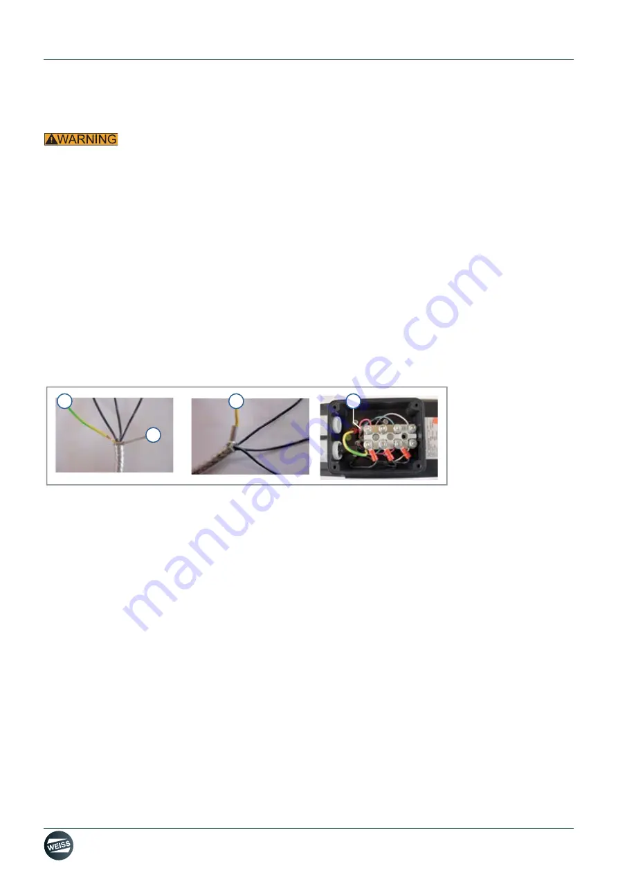
Fig. 36: Connecting the motor cable to the motor
The following measures are absolutely necessary to avoid EMC problems:
Cable for the holding brake:
•
A suitable cable must be used for the 24 V holding brake (2x1 mm² or 5x1 mm² if a temperature switch is connec-
ted).
The lines for the brake must not be routed together with the motor cable!
Use a separate cable!
Cable for the temperature switch:
The lines for the temperature switch must not be routed together with the motor cable!
Use a separate cable or a free wire in the cable for the holding brake!
Cable for the sensor:
The lines for the sensor must not be routed together with the motor cable!
Use a separate cable!
1
PE wire
3
PE wire, shield, ferrule
2
Shield
4
PE clamping point
1
3
2
4


