


69
Making 3D Stereo Measurements
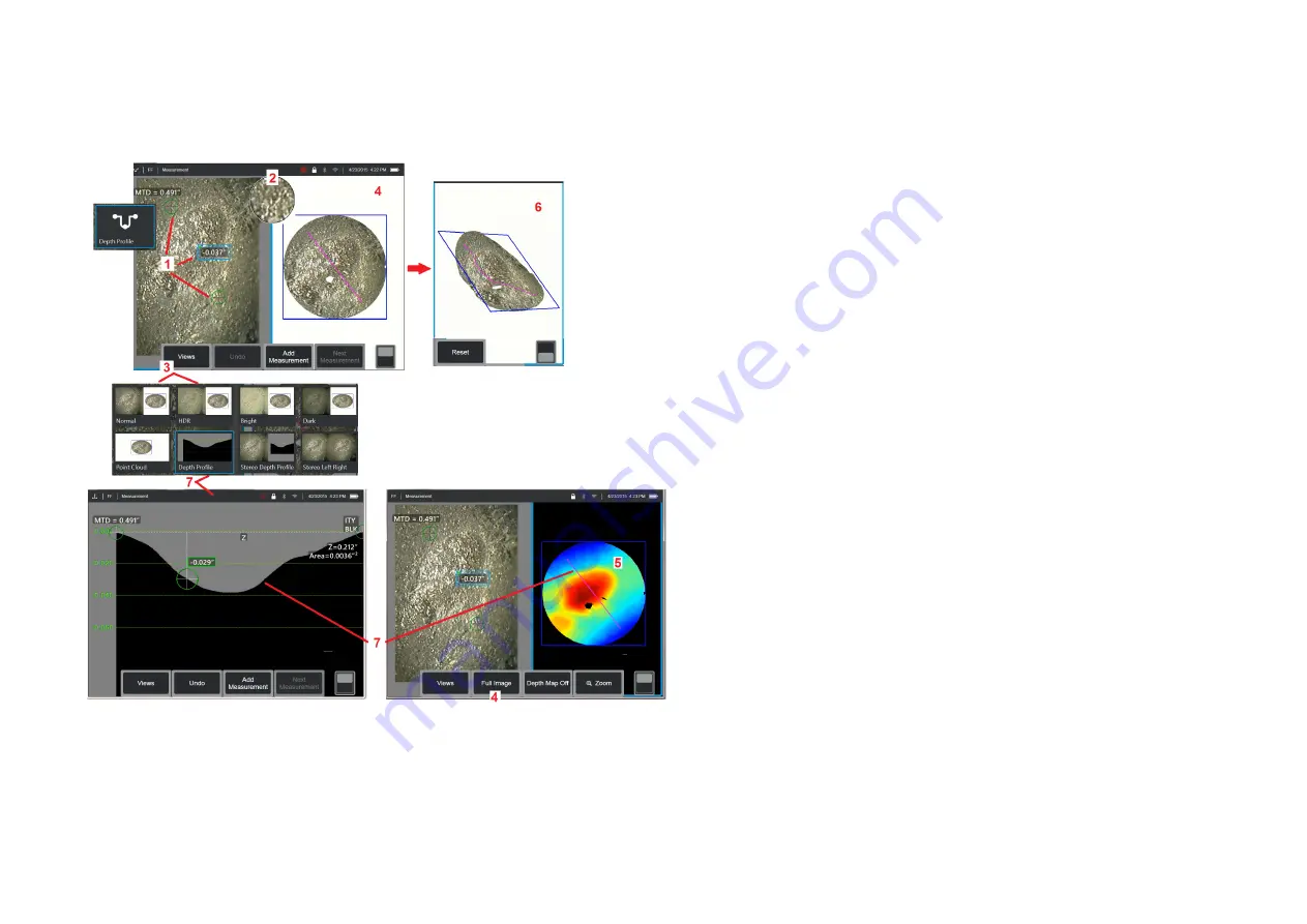
(Depth Profile Example)
Note:
While the following applies to a Depth Profile measurement, refer to
this procedure and the section titled
Types of 3D Measurement
for other
types.
1
– To create a Depth Profile measurement, place the first and second
cursors on flat surfaces on the same plane on opposite sides of the area
of interest.
2
– Patented Zoom Window allows for precision positioning of the active
cursor. Tap the window’s edges (or tap on the cursor, then control with
the joystick) to adjust the active cursor position.
Click here to learn about
turning the Zoom window on or off.
3
– Use to select from available Views.
Click here to learn about Views.
Note:
Depth Profile view (described in a following section) is only available
if the active measurement is a Depth Profile measurement.
Note:
Measurements can be performed with any of the Image Views
selected. However, the 3D coordinates used for measurement and shown
in the point cloud views are always computed using the Normal image.
4
– Point Cloud view, described below, allows the user to evaluate the
level of noise relative to indication size while verifying proper cursor
and profile position for the desired measurement. Choose between
Measurement Image and Full Image to view only the area around the
active measurement or the entire image.
5
– When a Point Cloud is displayed and active, turning on the Depth Map
uses color to convey the approximate depth of an indication.
Note:
When Full Image is selected, all measurements appear in the Point
Cloud view and the Depth Map colors represent the Tip-to-Target Distance.
When Measurement Image is selected, only the active measurement
appears and the Depth Map colors represent distances relative to the
measurement reference plane.
6
– When a Point Cloud view is displayed, drag a single finger over the
touchscreen (or use the joystick) to rotate the image in three dimensions.
Alternatively, place two fingers on the display and move simultaneously to
reposition or rotate the image within the plane in which it is viewed. Select
Reset to return the repositioned point cloud view to its original position.
7
– The Depth Profile view is available only after a Depth Profile measurement
has been made. This view provides a cross-section with the line connecting
the two reference cursors serving as a sectioning line.


