


67
3D Stereo Measurement Procedure, Part 1
Prior to collecting 3D Stereo measurements, a calibrated 3D Stereo OTA must be attached to your MViQ. Properly position the tip for measurement
(click here to see how to position the tip)
, which may be aided by temporarily displaying a single image by turning Single View mode ON
(click here to
select Single View).
The image capture and cursor placement process is described elsewhere – become familiar with this information before making
stereo measurements.
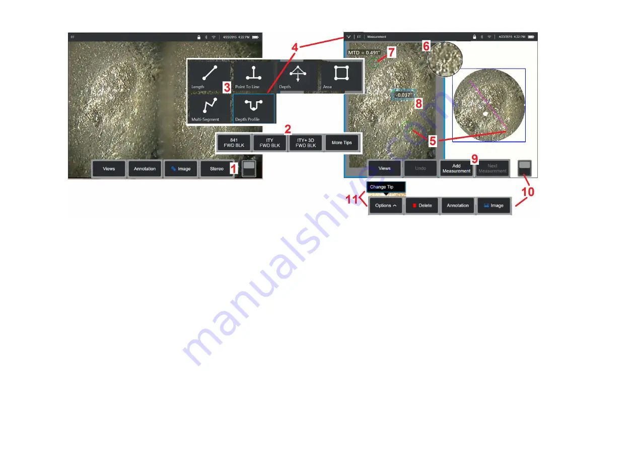
1
– Select the Stereo soft key (if working with a frozen image) or the Measure soft key (if working with a recalled image captured with a 3D Stereo optical
tip). Live stereo (and all other) images must be frozen prior to beginning the measurement process.
2
– After selecting Stereo, soft keys on the iQ’s display show the serial numbers for all 3D Stereo and stereo OTA's that have been calibrated to the
installed probe. 3D Stereo OTA's include a + 3D designation on the soft key. Be sure to select the serial number of the 3D Stereo OTA currently installed. If,
after collecting images for measurement, you determine that the wrong serial number was selected, refer to items 10 and 11.
Note: When an application calls for placement of measurement cursors within an area that does not include measurable image pixels, inserting a
measurement plane extends an object beyond its existing edges.
Click here to learn more about Placing a Measurement Plane.
3
– Begin the measurement process by choosing the type of measurement desired
(Click here for a description of each type of 3D Measurement)
4
– When a measurement type is selected (in this case, a Depth Profile measurement), this icon describes the type chosen.
5
– First cursor appears on the left screen, where all user-placement of cursors will occur. Drag with your finger (or joystick) to position the active cursor
to the desired location. This cursor can be reactivated (active cursor appears larger than other cursors) and moved at any time.
Note: Indication of Non-Measurable Area: When working with a 3D Stereo measurement image, certain parts of the image may not be measurable.
If portions of the image are unsuitable for stereo measurement, the measurement system will display a red colored zone in those areas. The system
will not compute a measurement result when a cursor is positioned in a red colored area.


