


66
3D Stereo Measurements
Stereo measurements require the use of StereoProbe measurement OTA's to capture stereoscopic
images of a target. 3D Stereo and Stereo both utilize the same Stereo OTA's, which provide two images of
the same scene from slightly different perspectives. They both rely on triangulation and the matching of
surface points in both images to determine 3D coordinates used for measurement. But, the use model and
processing are very different. With Stereo, the system performs matching and computes 3D coordinates
only at the locations of measurement cursors. With 3D Stereo, more advanced calibration and processing
algorithms are utilized to compute a full 3D point cloud prior to beginning the measurement making its
use more like 3DPM than stereo. The advanced processing also includes more intelligent matching and
data smoothing to greatly reduce measurement variation. As with 3DPM, the MViQ allows 3D visualization
of the 3D Stereo point cloud (hence the name 3D Stereo) to improve understanding of the viewed surface
and the measurement being performed.
Maximum Target Distance - MTD Number
A
s with other measurement types, 3D Stereo accuracy improves as tip-to-target distance is reduced. In
general, the best accuracy is achieved by getting as close to the surface as possible while keeping the
area of interest in sharp focus. Like 3DPM, 3D Stereo provides an MTD number for each measurement to
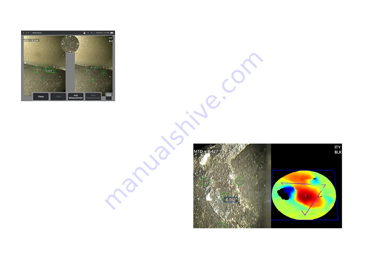
help gauge the likely accuracy of that measurement (see the upper left corner of the figure below). MTD stands for Maximum Target Distance and is the
distance from the stereo tip to the cursor that is furthest from the tip. Small measurements, especially depth or depth profile (~0.020” or smaller) types,
require low MTDs (< 0.5”) for good accuracy. Large length measurements can be accurately made with larger MTDs. The Point Cloud feature should be
used to verify that the level of noise present is small relative to the size of the defect being measured. Unlike Stereo, 3D Stereo does not use Accuracy Index.
When an application calls for placement of measurement cursors within an area that does not include measurable image pixels, inserting a measurement
plane extends an object beyond its existing edges (like the surface of a broken compressor blade or the space between a blade tip and a stationary
rub strip).
The 3D Stereo Measurement Process
You can take 3D Stereo measurements on a frozen image or on a recalled image,
provided the recalled image was saved with 3D Stereo measurement data. The
3D Stereo Measurement process includes:
Step 1—Attaching a calibrated 3D Stereo OTA. Each measurement
OTA must be factory calibrated to a particular probe and may
be calibrated to more than one probe. To ensure measurement
accuracy, verify the tip’s accuracy each time it is installed. Refer to
Appendix E
for verification procedures.
Step 2—Capturing an acceptable image.
(Click here to learn more about Images
Suitable for Stereo Measurement)
Step 3—Identifying the attached optical tip, selecting desired measurement type
and placing measurement cursors.
Step 4—Use the Point Cloud view to confirm an acceptable level of noise for the
image being measured.


