


CARDIO WAVE EXCITE Class & Trend: Service & maintenance manual- rev.2.0
Pagina 3.9
3.2.
BRAKE CONTROL
3.2.1.
M
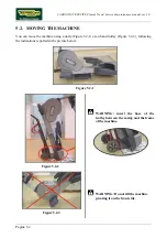
ECHANICS
The motion of the pedals imparts a rotation to the primary shaft via the belts connected to the 2
pedals. The primary shaft is connected to the secondary shaft and so to the brake, by means of a
belt. The speed sensor attached to the frame detects the heads of the screws which secure the disk to
the flywheel, and generates a signal proportional to the speed.
3.2.2.
C
ONTROLS
The control block diagram is as follows:
To obtain a given exercise effort level, the display board sends the required value of exercise speed
in step per minute to the Brake board via the RS-485 serial link. Based on the commands received
the brake board will then apply the appropriate excitation current to the brake winding, which
generates an electromagnetic field.
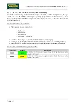
When the brake interface board receives the signal to generate resistance, the green
LED illuminates.
The electromagnetic field produced by the winding and the rotation of the disk will induce eddy
currents in the disk itself, giving rise to a force that tends to brake its motion. This generates the
exercise resistance.
Display Board
Brake board
RS-485
CN9
CN4
1-2/CN2
Brake
Excitation Current
3-4/CN2
Pulses
Speed
sensor
Green LED
Summary of Contents for CLASS & TREND
Page 1: ...SERVICE MAINTENANCE MANUAL REV 2 0 ...
Page 2: ......
Page 4: ......
Page 50: ...CARDIO WAVE EXCITE Class Trend Service maintenance manual rev 2 0 Pagina 4 6 LIBYA DVB T ...
Page 52: ......
Page 213: ......


