


CARDIO WAVE EXCITE Class & Trend: Service & maintenance manual- rev.2.0
Pagina 3.6
3.1.5.
D
UAL
TGS
READER
It’s the device which allows the machine to interact with the Wellness System.
This board enables the machine to read the user's TGS key for performing workouts programmed
with the propers SW of the Wellness System.
With Dual TGS reader it is possible to use both the Botom and the Mifare TGS keys.
3.1.6.
C
ARDIO RECEIVER
This board manages the signal received from the telemetric transmitter used by the person
exercising. It receives the power supply signal from the Display Board and outputs a negative logic
pulse for every heart beat that is detected: the signal level is normally 5 Vdc, with a pulse at 0 Vdc
(having a width of approximately 30 msec) at each heart beat.
The receiver reception area is approximately with a 90 cm radius. If there is electromagnetic noise
(produced by high voltage lines, radio transmitters, monitors, motors etc.) within this area, the
receiver becomes saturated and no longer receives any signal.
The Salutron 8500 models, manage both the telemetric transmitter and the hand sensors signals, in
the same way.
3.1.7.
B
RAKE BOARD
There are 2 versions of the Brake Board, one which is used on the mains powered version and the
other on the self-powered version. In either case, the Brake Board consists of:
•
Power supply section which generates the low voltages used by the machine: +5 Vdc and +12
Vdc. Depending on the machine version, these voltages will be generated either from the 110
VAC or 220 VAC mains supply, or from the alternator-battery.
•
Section for RS-485 serial communications with the Display Board for:
commands determining the resistance that is required of the brake;
brake error messages;
commands for modifying the circuit board configuration parameters;
commands for viewing the errors logged by the circuit board.
•
Section which generates the current for the brake winding: varying the current produces a
proportional variation in the resistance of the brake. The excitation current supplied to the
brake is a function of the effort level selected on the display and the RPM value measured by
the speed sensor (angular velocity of the brake disk) and is determined by the values stored in
the braking table.
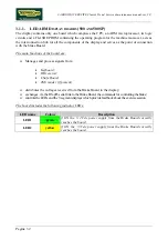
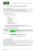
The board includes the following indicator LEDs:
LED name
Colour
Description
LED1
green
if ON the board is supplying the brake winding.
if BLINKING the Brake Board is in an error condition.
LED2
yellow
if ON there is the +5 Vdc supply from the circuit Board.
Summary of Contents for CLASS & TREND
Page 1: ...SERVICE MAINTENANCE MANUAL REV 2 0 ...
Page 2: ......
Page 4: ......
Page 50: ...CARDIO WAVE EXCITE Class Trend Service maintenance manual rev 2 0 Pagina 4 6 LIBYA DVB T ...
Page 52: ......
Page 213: ......


