290 Fieldbus Communication
WAGO-I/O-SYSTEM 750
750-882 Media Redundancy ETHERNET Controller
Manual
1.5.0
12.3.5.12 Coupler/Controller Configuration (64
hex
)
The fieldbus coupler configuration class allows reading and configuration of some
important fieldbus/controller process parameters. The following listings explain in
details all supported instances and attributes.
Instance 0 (Class Attributes)
Table 226: Coupler/Controller configuration (64
hex
) – Class
Attribute ID Acces
s
Name
Data type Description
Default value
1
Get
Revision
UINT
Revision of this object
1 (0x0001)
2
Get
Max Instance UINT
Max. number of instances
1 (0x0001)
Instance 1
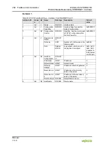
Table 227: Coupler/Controller configuration (64
hex
) – Instance 1
Attribute ID Acces
s
NV Name
Data type Description
Default
value
5 (0x05)
Get
V
ProcessStat
e
USINT
State of coupler/controller, error
mask:
Bit 0: Local bus error
Bit 3: Module diagnostics (0x08)
Bit 7: Fieldbus error (0x80)
0
6 (0x06)
Get
V
DNS_i_
Trmnldia
UINT
Module diagnostics:
Bit 0..7: Module number
Bit 8..14: Module channel
Bit 15: 0/1 Error, repair/arisen
0
7 (0x07)
Get
V
CnfLen.
AnalogOut
UINT
Number of I/O bits for the analog
output
-
8 (0x08)
Get
V
CnfLen.
AnalogInp
UINT
Number of I/O bits for the analog
input
-
9 (0x09)
Get
V
CnfLen.
DigitalOut
UINT
Number of I/O bits for the digital
output
-
10 (0x0A)
Get
V
CnfLen.
DigitalInp
UINT
Number of I/O bits for the digital
input
-
11 (0x0B)
Set
NV Bk_Fault_
Reaction
USINT
Fieldbus error reaction
0: stop local I/O cycles
1: set all output to 0
2: no error reaction
3: no error reaction
4: PFC task takes over control of
the outputs (apply to controllers)
1
12..26
(0x0C...0x1A)
Reserved for compatibility to DeviceNet
40..43
(0x28...0x2B)
Reserved for compatibility to DeviceNet
45 (0x2D)
Get
V
Bk_Led_Err
_Code
UINT
I/O LED error code
0
46 (0x2E)
Get
V
Bk_Led_Err
_Arg
UINT
I/O LED error argument
0


